
Datasheet

BCR450
LED Driver IC
Evaluation Board
Datasheet 15 Rev. 3.1, 2013-02-21
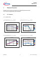
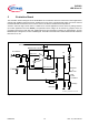
5 Evaluation Board
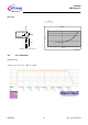
The evaluation board is designed to test the BCR450 as a stand alone device for lower LED current applications
and also with additional external “booster“ transistors for high current, high brightness LEDs. Up to three external
transistors BCX68 or BC817SU each could be used on the PCB to minimize thermal problems.
3 LEDs in series for high current mode or 3 LEDs for low cur
rent applications can be chosen by setting resistors
(for further application hints see AN105). The particular sense voltage can be derived by jumpers which are
provided in the layout for each test case. Additional test circuit is included to measure AC characteristics, and the
ENABLE input is designed to connect a PWM signal. The PCB is manufactured in double sided FR4 with substrate
thickness of 1.0 mm.
Vbat
BCR450 LED Controller
LEDs
Rsensehigh
LEDs
NPN
Power
Transistors
Jumper-H
Jumper-L
Rsenselow
BCX68-25
or
BC817SU
AC- Measure
PWM
P2
P1
BCR450_Application circuit.vsd
=
Vref
Vs, Pin 6
Vsense, Pin 4
Iout, Pin 1
EN, Pin 3
GND, Pin 2 & 5
+
-
Figure 3 Evaluation board schematic