
Datasheet


Application Note 6 Rev. 2.1, 2006-10-20
Application Note No. 058
Predicting Distortion in PIN-Diode Switches
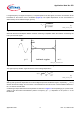
If a high-frequency AC-signal of frequency f is superimposed to the DC signal, the carrier concentration at the
boundaries of the intrinsic zone is modulated (
Figure 6). The spatial dependence of this concentration is
determined by the AC-diffusion length, given by
Figure 5 Formula (4)
Where D denotes the ambipolar diffusion constant. Assuming no depletion within the instrinsic zone during the
half-cycle of the RF-signal.
Figure 6 AC-modulation of the carrier concentration in the intrinsic region of the PIN-diode
The high frequency diffusion region shows the current-voltage dependence.
Figure 7 Formula (5)
With i(t) and v(t) the time dependent current and voltage drop across the diffusion region, respectively; v
T
= kT / q
denotes the thermal voltage. This non-linear i-v-characteristics is the main source of intermodulation distortion in
the “on”-state of the PIN-diode.
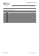
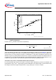
Considering a simple diode-switch with equivalent circuit shown in Figure 11 and expanding (5) in a power series,
yields for the third-order intermodulation product at frequency 2f
1
- f
2
, dependent on the power P
0
of the
fundamental
AN058_formula_4.vs
d
(4)
)2(1
τπ
τ
fj
D
L
AC
+
=
AN058_AC_modulation.vs
d
p++
n++
intrinsic region
n, p
RF
L
AC
AN058_formula_5.vs
d
(5)
T
v
tv
W
I
fDti
2
)(
exp
2)(
τ
π
=