
Datasheet


Application Note 4 Rev. 2.1, 2006-10-20
Application Note No. 058
Predicting Distortion in PIN-Diode Switches
1 Predicting Distortion in PIN-Diode Switches
This application note describes the orgin of distortion in PIN-diode switches. Distrotion is related to physical
parameters of the diode and operating conditions and thus can be minimized by an appropriate diode selection.
A simple relation to calculate the intercept point
IP
3
from parameters given in the data sheet is provided and limits
for prediction of intermodulation power from the intercept point are shown.
1.1 Intercept Point IP
3
Generally the orgin of distortion in electronic circuits is the nonlinear transfer characterictics of v
in
to v
out
. This
response can be discribed by the power series:
Figure 1 Formula (1)
If two signals of equal amplitude v
0
and similar frequencies (f
1
and f
1
≈ f
2
) are applied, parasitic frequency
components occur in the output signal. Of these components, the third-order term in (1) is typically the
troublesome one, since it gives components
Figure 2 Formula (2)
This third-order products occur at frequencies 2f
1
- f
2
and 2f
2
- f
1
, which are so close to the desired signal, they
typically cannot be filtered out.
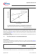
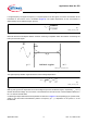
Due to their cubic dependence on v
0
(2), third order intermodulation components are strongly dependent on the
input power, Thus third-order inter-modulation is commonly characterized by the intercept-point
IP
3
, a fictitious
input power level, where the power of the third-order intermodulation product intercept with the power of the linear
transfer component (Figure 3)
AN058_formula_1.vsd
(1)
....
3
3
2
21
+++=
inininout
vAvAvAv
AN058_formula_2.vsd
(2)
[]
]...)2(2cos[])2(2cos[
4
3
1221
3
03
3
3
tfftffvAvA
in
−+−=
ππ