
Datasheet


AUIR3313(S)
www.irf.com
7
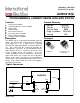
Figure 3 – Active clamp waveforms
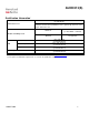
Figure 4 – Min. pulse and Wait function
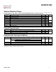
Figure 5 – Protection Timing Diagrams
Vout
Iout
Vin
Vcc
Vcc - V clamp
t clamp
See Application Notes to evaluate power dissipation
Vcc-Vin
t min. pulse
Iout
t min. pulse
Wait
Vcc-Vin
t < t reset
Iout
Wait
Tj
t > t reset
Over-current shutdown
t < t reset
Wait
t > t reset
Over-temperature shutdown