
Datasheet


AUIR3313(S)
www.irf.com
3
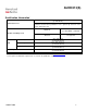
Absolute Maximum Ratings
Absolute maximum ratings indicate sustained limits beyond which damage to the device may occur. All voltage parameters
are referenced to Vcc lead. (Tj=-40°..150°C, Vcc=6..26V Tambient=25°C unless otherwise specified).
Symbol
Parameter
Min.
Max.
Units
Vcc-Vin
Maximum Vcc voltage
-16
37
V
Vcc-Vin cont.
Maximum continuous Vcc voltage
-16
32
Vcc-Vfb
Maximum Ifb voltage
-16
33
Vcc-Vout
Maximum output voltage
-0.3
37
Ids cont.
Maximum body diode continuous current Rth=60°C/W (1)
2.8
A
Ids pulsed
Maximum body diode pulsed current (1)
100
Pd
Maximum power dissipation Rth=60°C/W
2
W
Tj max.
Max. storage & operating temperature junction temperature
-40
150
°C
Min Rfb
Minimum on the resistor on Ifb pin
0.3
k
Ifb max.
Max. Ifb current
-50
50
mA
(1) Limited by junction temperature. Pulsed is also limited by wiring
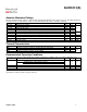
Thermal Characteristics
Symbol
Parameter
Typ.
Max.
Units
Rth1
Thermal resistance junction to ambient D²-Pak Std footprint
60
°C/W
Rth2
Thermal resistance junction to case D²-Pak
0.7
Rth2
Thermal resistance junction to case TO220
0.7
Recommended Operating Conditions
These values are given for a quick design. For operation outside these conditions, please consult the application notes.
Symbol
Parameter
Min.
Max.
Units
Iout
Continuous output current
A
Tambient=85°C, Rth=5°C/W, Tj=125°C
23
Tambient=85°C, Rth=60°C/W, Tj=125°C
7
Rifb
Recommended Ifb resistor (2)(3)
0.3
3.5
k
Pulse min.
Minimum turn-on pulse width
1
ms
Fmax.
Maximum operating frequency
200
Hz
(2) If Rifb is too low, the device can be damaged.
(3) If Rifb is too high, the device may not switch on.