
Datasheet
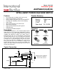


AUIPS6041(G)(R)(S)
www.irf.com
4
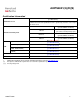
Static Electrical Characteristics
Tj=-40°C..150°C, Vcc=6..28V (unless otherwise specified), typical values are given for Vcc=14V and Tj=25°C
Symbol
Parameter
Min.
Typ.
Max.
Units
Test Conditions
Rds(on)
ON state resistance Tj=25°C
110
130
m
Vin=5V, Iout=2.5A
ON state resistance Tj=150°C
190
230
Vin=5V, Iout=2.5A
ON state resistance Tj=25°C, Vcc=6V
125
155
Vin=5V, Iout=1.5A
ON state resistance during reverse battery
Tj=25°C
140
180
Vcc-Gnd=-14V
Vcc op.
Operating voltage range
6
28
V
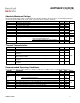
V clamp 1
Vcc to Out clamp voltage 1
37
39
43
Iout=20mA
V clamp 2
Vcc to Out clamp voltage 2
40
Iout=2.5A (see Fig. 1)
Icc Off
Supply current when Off and with Vout
connected to ground Rconnection <4Ω
4
9
µA
Vin=0V, Vout=0V,
Tj=25°C, Vcc=14V
Icc On
Supply current when On
2.2
5
mA
Vin=5V, Vcc=14V
Vih
Input high threshold voltage
2.5
3
V
Vil
Input low threshold voltage
1.5
2
In hyst.
Input hysteresis
0.2
0.5
1
Iin On
Input current when device is On
40
100
µA
Vin=5V
Idg
Dg leakage current
0.1
10
Vdg=5V
Vdg
Low level DG voltage
0.25
0.4
V
Idg=1.6mA
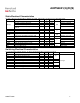
Switching Electrical Characteristics
Vcc=14V, Resistive load=6, Vin=5V, Tj=-40°C..150°C, typical values are given for Tj=25°C
Symbol
Parameter
Min.
Typ.
Max.
Units
Test Conditions
Tdon
Turn-on delay time
5
15
µs
see Fig. 3
Tr1
Rise time to Vout=Vcc-5V
3
10
Tr2
Rise time to Vout=0.9 x Vcc
4
30
dV/dt (On)
Turn On dV/dt
2.5
V/µs
EOn
Turn On energy
100
µJ
Tdoff
Turn-off delay time
10
20
µs
Tf
Fall time to Vout=0.1 x Vcc
3
10
dV/dt (Off)
Turn Off dV/dt
6.5
V/µs
EOff
Turn Off energy
50
µJ