
Datasheet
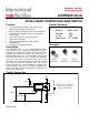


AUIPS6031(S)(R)
www.irf.com
3
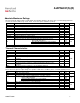
Absolute Maximum Ratings
Absolute maximum ratings indicate sustained limits beyond which damage to the device may occur. All voltage parameters
are referenced to Ground lead. Tj= -40°C..150°C, Vcc=6..35V (unless otherwise specified).
Symbol
Parameter
Min.
Max.
Units
Vout
Maximum output voltage
Vcc-35
Vcc+0.3
V
Voffset
Maximum logic ground to load ground offset
Vcc-35
Vcc+0.3
Vin
Maximum input voltage
-0.3
5.5
Vcc max.
Maximum Vcc voltage
36
Vcc cont.
Maximum continuous Vcc voltage
28
Vcc sc.
Maximum Vcc voltage with short circuit protection
30
Iin max.
Maximum IN current
-3
10
mA
Idg max.
Maximum diagnostic output current
-3
10
Vdg
Maximum diagnostic output voltage
-0.3
5.5
V
Pd
Maximum power dissipation (internally limited by thermal protection)
25
W
Rth=5°C/W AUIPS6031
Rth=40°C/W AUIPS6031S 1”sqrt. footprint
3.1
Rth=50°C/W AUIPS6031R 1”sqrt. footprint
2.5
Tj max.
Max. storage & operating temperature junction temperature
-40
150
°C
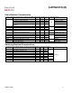
Thermal Characteristics
Symbol
Parameter
Typ.
Max.
Units
Rth1
Thermal resistance junction to ambient AUIPS6031 TO220 free air
50
°C/W
Rth2
Thermal resistance junction to case AUIPS6031 TO220
3.8
Rth1
Thermal resistance junction to ambient AUIPS6031S D²Pak std. footprint
60
Rth2
Thermal resistance junction to ambient AUIPS6031S D²Pak 1” sqrt.
footprint
40
Rth3
Thermal resistance junction to case AUIPS6031S D²Pak
3.8
Rth1
Thermal resistance junction to ambient AUIPS6031R D-Pak std. footprint
70
Rth2
Thermal resistance junction to ambient AUIPS6031R D-Pak 1” sqrt.
footprint
50
Rth3
Thermal resistance junction to case AUIPS6031R D-Pak
3.8
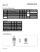
Recommended Operating Conditions
These values are given for a quick design. For operation outside these conditions, please consult the application notes.
Symbol
Parameter
Min.
Max.
Units
VIH
High level input voltage
4
5.5
VIL
Low level input voltage
0
0.9
Iout
Continuous drain current, Tambient=85°C, Tj=125°C, Vin=5V
A
Rth=5°C/W AUIPS6031
8.9
Rth=40°C/W AUIPS6031S 1” sqrt. footprint
3.1
Rth=50°C/W AUIPS6031R 1” sqrt. footprint
2.8
Rin
Recommended resistor in series with IN pin
4
10
k
Rdgs
Recommended resistor in series with DG pin for reverse battery protection
4
20
Rdgp
Recommended pull-up resistor for DG
4
20
Rol
Recommended pull-up resistor for open load detection
5
100
F max.
Max. switching frequency
2.5
kHz