
Datasheet


AUIPS1031(S)(R)
www.irf.com
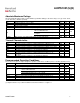
8
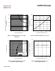
0
5
10
15
20
25
30
-50 0 50 100 150
5°C/W
10°C/W
1" sq footprint
std footprint
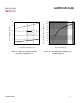
0
10
20
30
40
0.1 1 10 100
50°C/W 25°C ambient
50°C/W 85°C ambient
50°C/W -40°C ambient
Ids, cont. Output current (A)
nt (A)
Figure 9 – Max. continuous output current (A)
Vs Ambient temperature (°C)
Protection response time (s)
Figure 10 – Ids (A) Vs over temperature
protection response time (s)
Ids, output curre
Tamb, Ambient temperature (°C)
Figure 11 – Max. ouput current (A)
Vs Inductive load (mH)
Ids, output current (A)
Inductive load (mH)
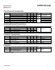
Figure 12 – Transient thermal impedance (°C/W)
Vs time (s)
Zth, transient thermal impedance (°C/W)
1
10
100
0.001 0.01 0.1 1
Time (s)
0.01
0.1
1
10
100
1E-05 0.0001 0.001 0.01 0.1 1 10 100