
Datasheet


AUIPS1031(S)(R)
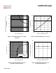
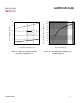
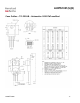
All curves are typ
ical values. Operating in the shaded area is not recommended.
T
j
Isd
Tsd
165°C
Ids
Vin
Ishutdown
Tshutdown
t<T reset
t>T reset
Vdia
g
fault
normal
Vds
Ids
Vin
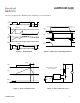
Tr-in
80%
20%
80%
20%
Td on
Tr
Td off
Tf
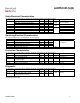
Figure 1 – Timing diagram Figure 2 – IN rise time & switching definitions
Vds
Ids
Vin
IN
D
S
R
L
0V
5V
14V
+
-
V load
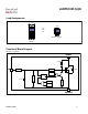
Rem : During active clamp,
Vload is negative
Vds
Ids
Vin
Vcc
Vds clamp
T clamp
See Application Notes to evaluate power dissipation
Figure 3 – Active clamp waveforms Figure 4 – Active clamp test circuit
www.irf.com
6