
Datasheet
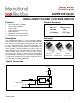


AUIPS1031(S)(R)
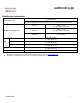
Static Electrical Characteristics
Tj= -40..150°C, Vcc=6..28V (unless otherwise specified), typical value are given for Tj=25°C
Symbol Parameter Min. Typ. Max. Units Test Conditions
ON state resistance Tj=25°C
40 50
Rds(on)
ON state resistance Tj=150°C (2)
76 95
m
Vin=5V, Ids=8A
Idss1 Drain to source leakage current
0.1 2 Vcc=14V, Tj=25°C
Idss2 Drain to source leakage current
0.2 4
µA
Vcc=28V, Tj=25°C
V clamp1 Drain to source clamp voltage 1 36 39
Id=20mA
V clamp2 Drain to source clamp voltage 2
40 42 Id=1A
Vin clamp IN to source pin clamp voltage 5.5 6.5 7.5 Iin=1mA
Vth Input threshold voltage
1.7
V
Id=10mA
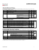
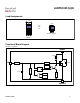
Switching Electrical Characteristics
Vcc=14V, Resistive load=1.5, Rinput=0, Vin=5V, Tj=25°C
Symbol Parameter Min. Typ. Max. Units Test Conditions
Tdon Turn-on delay time to 20% 3 10 30
Tr Rise time 20% to 80% 6 20 40
Tdoff Turn-off delay time to 80% 20 70 200
Tf Fall time 80% to 20% 6 15 30
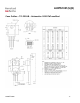
µs See figure 2
Eon + Eoff Turn on and off energy
0.7
mJ
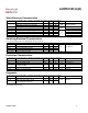
Protection Characteristics
Tj= -40..150°C, Vcc=6..28V (unless otherwise specified), typical value are given for Tj=25°C
Symbol Parameter Min. Typ. Max. Units Test Conditions
Tsd Over temperature threshold 150(2) 165
°C See figure 1
Isd Over current threshold 9.5 18 27 A See figure 1
OV Over voltage protection (not active when
the device is ON )
34 37
V
Vreset IN protection reset threshold
1.7
V
Treset Time to reset protection 15(2) 50 200 µs Vin=0V
Diagnostic
Tj= -40..150°C, Vcc=6..28V (unless otherwise specified), typical value are given for Tj=25°C
Symbol Parameter Min. Typ. Max. Units Test Conditions
Iin, on ON state IN positive current 10 32 80
Iin, off OFF state IN positive current
( after protection latched )
120 230 350
µA
Vin=5V
Vin=5V
(2) Guaranteed by design
www.irf.com
4