
Manual

4 - 6
IPN 074-155L
CrystalSix Operating Manual
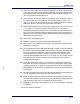
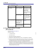
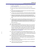
Figure 4-2 Alignment Pin Installation
4.4.2 Disassembly Instructions
In the following steps, reference Figure 1-3 on page 1-6 and Figure 4-2 on page
4-6.
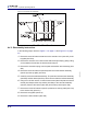
1 Remove the two #4 fasteners that secure the actuator cover (item #15) to the
top plate (item #10).
2 Remove the actuator cover. Remove the heat shield (item #8) by gently pulling
on the outside of the shield, the shield should snap off.
3 Remove the extension spring from the pawl and actuator stem assembly (item
#24).
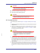
4 Remove the two #4 fasteners (item #20) that secure the bellows assembly
(item #19) to the top plate (item #10).
5 Carefully remove the bellows assembly. The pawl and actuator stem assembly
(item #24) and the detent (item #41) will be removed with the bellows assembly.
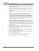
6 Using the 1/16" allen wrench, loosen the set screws (item #33) that secures the
ratchet (item #22) and the stop ratchet (item #38) to the carousel assembly
(item #5). Remove the ratchet (item #22) and the stop ratchet (item #38).
7 Remove the three #4 fasteners (item #14) that secure the top plate (item #10)
to the sensor body (item #11).
8 Remove the top plate (item #10).
9 Remove the Teflon washer (item #39).