
Manual

4 - 4
IPN 074-155L
CrystalSix Operating Manual
CAUTION
Incorrect rotation direction with the stops disabled will
cause permanent damage rendering transducer
inoperative. Refer to Figure 1-2 on page 1-5 for proper
direction of rotation.
The unit, when properly aligned, will index the crystal to a position that is centered
within the aperture provided in the heat shield. The unit must be aligned if this
condition does not exist.
Reference Figure 1-3 on page 1-6.
Equipment Required:
5/64" allen wrench (Included in 750-268 Kit)
1/16" allen wrench (Included in 750-268 Kit)
3/32" allen wrench (Included in 750-268 Kit)
Alignment tool assembly 750-254-G1 (Included in 750-268 kit)
Regulated air supply 80-90 PSIG (5.5 bar - 6.2 bar) [550 kPa - 620 kPa]
NOTE: 75 PSIG (5.2 bar) [520 kPa] for alignment purposes only)
4.4.1 Alignment Instructions
With the required equipment at hand, proceed as follows:
1 Temporarily connect an air supply to the bellows assembly supply tube.
Regulate the air pressure to 75 PSIG (5.2 bar) [520 kPa].
2 Remove the actuator cover (item 15) and related hardware.
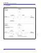
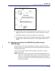
3 Insert the 0.125" diameter alignment pin (of the 750-254-G1 assembly) in the
alignment hole (if not already installed) as shown in Figure 4-2 on page 4-6.
The carousel may need to be rotated to achieve the alignment condition shown
in Figure 4-2.
4 Loosen the set screws (two set screws per item) of the ratchet (item #22) and
the stop ratchet (item #38).
5 Loosen the #2 fastener (item #42) that attaches the detent (item #41) to the
bellows assembly item #19). Do NOT remove detent.
6 Actuate the bellows assembly by applying 24 volts to the leads of the solenoid
valve of the solenoid valve assembly. Consult Figure 3-1 on page 3-4 for wiring
assignments. The air pressure must be sustained.