
Manual

3 - 3
IPN 074-155L
CrystalSix Operating Manual
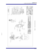
3.2 Installation with 2 3/4” Feedthrough
Installation of the solenoid valve requires a 2 3/4" feedthrough inclusive of two
coaxial feedthroughs (IPN 002-080, see Figure 5-2 on page 5-2). The second
coaxial feedthrough is not used, and should be protected from damage as a result
of process material. Follow the steps below:
1 Install the Feedthrough.
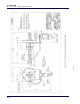
2 Add the valve bracket (modified) to the desired location as illustrated in Figure
3-3 on page 3-6.
3 Tighten the feedthrough bolts.
4 Install the air fitting to the female thread adapter.
5 Connect 1/8" diameter tubing from the valve output (A) to the feedthrough
fitting. See the CAUTION in section 3.1 above.
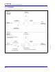
6 Attach the valve’s supply (P) (normally closed (NC) port) to the 80-90 PSIG
(5.5 bar - 6.2 bar) [550 kPa - 620 kPa] source of air. Verify that the orifice
(IPN 059-189) has been installed into this NC valve port. (See Figure 3-1b of
Figure 3-1 on page 3-4.)
NOTE: Maximum temperature for the solenoid valve assembly is 105 °C for
bakeout and operation.
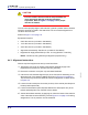
3.3 Electrical and Pneumatic Connections
3.3.1 Electrical
To complete installation of the assembly, make electrical connections where
indicated in Figure 3-3 on page 3-6 to either 24 V(ac) or V(dc). Current required is
approximately 70 mA.
CAUTION
Maximum applied voltage must not exceed 26 V(ac).