
Manual

3 - 1
IPN 074-155L
CrystalSix Operating Manual
Chapter 3
Installation of the Solenoid Valve Assembly
The solenoid valve assembly (IPN 750-420-G1) and the feedthrough should be
installed at the same time. The same valve assembly is used for both the 1" and
the (recommended) 2 3/4" feedthroughs. However, if the assembly is to be used
with the 2 3/4" feedthrough, you will need to modify the valve bracket as follows.
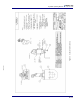
For the following steps, see Figure 3-2 on page 3-5. (DWG. 750-420-G1)
1 Align the score line on the valve assembly bracket (item #5) over the edge of a
table or other square edge.
2 Using pliers, grasp the part of the bracket extending over the edge and push
down. The bracket will break along the score line. Use a file to smooth any
rough edges which occur along the break.
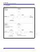
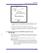
NOTE: In order for the CrystalSix sensor to operate properly, a .022" diameter
orifice (IPN 059-189 provided in Kit 750-268) must be installed in line
between the air supply and the solenoid valve assembly. This is
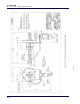
accomplished by the following procedure. See Figure 3-1 on page 3-4.
1 Unthread the tube fitting attached to the normally closed (N.C.) P Supply port
of the 3-way solenoid valve (item #7).
2 Install the orifice by threading it into the normally closed (N.C.) port of the 3-way
solenoid valve.
3 Thread the tube fitting previously removed into the orifice.
NOTE: Do not install the orifice into the normally open output port. This will require
a longer time interval for depressurization of the bellows assembly and
may lead to an apparent sensor failure.