O P E R A T I N G M CrystalSix Sensor ® IPN 074-155L A N U A L
O P E R A T I N G M A N U CrystalSix ® Sensor IPN 074-155L ® www.inficon.com ©2001 INFICON reachus@inficon.
Trademarks The trademarks of the products mentioned in this Operating Manual are held by the companies that produce them. INFICON®, CrystalSix® and Composer® are trademarks of INFICON Inc. ConFlat® is a registered trademark of Varian Associates. Teflon® is a registered trademark of Dupont. Scotch-Brite™ is a trademark of 3M. SWAGELOK® and CAJON® are registered trademarks of Swagelok, Co. Inconel® is a registered trademark of International Nickel Co. Microdot® is a registered trademark of Microdot Corp.
Warranty WARRANTY AND LIABILITY - LIMITATION: Seller warrants the products manufactured by it, or by an affiliated company and sold by it, and described on the reverse hereof, to be, for the period of warranty coverage specified below, free from defects of materials or workmanship under normal proper use and service.
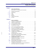
CrystalSix Sensor Operating Manual Table Of Contents Chapter 1 Sensor Specifications 1.1 1.1.1 1.1.1.1 Specifications for CrystalSix Sensor 750-446-G1 . . . . . . . . . . . . . . . . . . . . 1-1 Installation Requirements . . . . . . . . . . . . . . . . . . . . . . . . . . . . . . . . . . . . . . . 1-2 Feedthrough . . . . . . . . . . . . . . . . . . . . . . . . . . . . . . . . . . . . . . . . . . . . . . . . . 1-2 1.1.1.2 Other. . . . . . . . . . . . . . . . . . . . . . . . . . . . . . . . . . . . . . .
CrystalSix Sensor Operating Manual Chapter 3 Installation of the Solenoid Valve Assembly 3.1 3.2 3.3 3.3.1 3.3.2 Installation with 1” Bolts . . . . . . . . . . . . . . . . . . . . . . . . . . . . . . . . . . . . . . . . 3-2 Installation with 2 3/4” Feedthrough . . . . . . . . . . . . . . . . . . . . . . . . . . . . . . . 3-3 Electrical and Pneumatic Connections. . . . . . . . . . . . . . . . . . . . . . . . . . . . . 3-3 Electrical. . . . . . . . . . . . . . . . . . . . . . . . . . . . . . . . . . . . . .
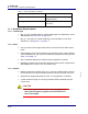
CrystalSix Operating Manual Chapter 1 Sensor Specifications 1.1 Specifications for CrystalSix Sensor 750-446-G1 CAUTION Incorrect rotation direction with the stops disabled will cause permanent damage rendering transducer inoperative. See Figure 1-2 on page 1-5 for proper direction of rotation. The CrystalSix® sensor is a (six crystal) quartz crystal deposition monitor transducer. When the monitor crystal being used fails a new crystal is advanced into position, fully replacing that crystal’s function.
CrystalSix Operating Manual Table 1-1 Sensor specification (continued) Water, air and coax length Standard 30" (76 cm) Crystal exchange Front-loading, extraction tool required (supplied with unit) Mounting Six #4-40 tapped holes on the back of the sensor body 1.1.1 Installation Requirements 1.1.1.
CrystalSix Operating Manual 1.1.2 Materials Table 1-2 Materials Plate, Holders, Material Shield, Mechanical Parts 304 type stainless steel Springs, Electrical Contacts Au plated Be-Cu, Au Plate Inconel®, 303 stainless steel Water and air tubes S-304, 0.125" (0.32 cm) O.D. x .016" (.04 cm) Wall Thickness 30" Long (76 cm) Seamless Stainless Steel Tubing Connector (Microdot) Stainless steel Insulators >99% A1 O Cable Teflon® insulated copper Crystal 0.
CrystalSix Operating Manual Table 1-3 Contents of Accessory Kit (continued) Qty IPN Description #4-40x0.500" Long Socket Head Cap Screw, Stainless Steel 2 084-084 #4-40x0.
IPN 074-155L Figure 1-2 Outline Multi Crystal Sensor 5RWDWLRQ 'LUHFWLRQ CrystalSix Operating Manual 1-5
IPN 074-155L Figure 1-3 Assembly CrystalSix Sensor CrystalSix Operating Manual 1-6
CrystalSix Operating Manual Chapter 2 Sensor Installation Successful operation of any crystal sensor depends on proper placement, compatibility of its construction with its operating environment and connection to proper utilities. NOTE: The sensor head, water tubes, cable, etc. should be clean and grease free when installed in the vacuum chamber. These parts should be handled while wearing clean nylon gloves.
CrystalSix Operating Manual 2.1.2 Care of the Ceramic Retainer CAUTION Do not use excessive force when handling the Ceramic Retainer Assembly since breakage may occur. Always use the crystal snatcher. To prevent scratching the crystal electrode, do not rotate the ceramic retainer after installation. Always use clean nylon lab gloves and plastic tweezers for handling the crystal. This avoids contamination which may lead to poor adhesion of deposited material to the electrode.
CrystalSix Operating Manual Figure 2-1 Using the Crystal Snatcher 4 Invert the crystal holder and the crystal will drop out. (Skip this step for first-time installations.) 5 Install the new crystal per section 2.1.1 on page 2-1 and section 2.1.2 on page 2-2. 6 Using clean nylon gloves, grasp the edge of the new crystal with a clean pair of plastic tweezers. Orient the crystal so the patterned electrode is facing up.
CrystalSix Operating Manual Figure 2-2 Using the Crystal Puller 2.2 Pre-installation Sensor Check Prior to installing the sensor in the vacuum system, you should make certain that it is in proper working condition by following the procedure outlined below. 2.2.1 IC/5 Deposition Controller 1 Connect the in-vacuum sensor head cable to the feedthrough or a coax adapter (microdot/BNC). 2 Connect one end of the 6" XIU cable (IPN 755-257-G6) to the BNC connector of the feedthrough.
CrystalSix Operating Manual 2.2.2 XTC/2 or XTC/C Deposition Controller 1 Connect the in-vacuum sensor head cable to the feedthrough or a coax adapter (microdot/BNC). 2 Connect one end of the 6" XIU cable (IPN 755-257-G6) to the BNC connector or the feedthrough. 3 Connect the other end of the 6" XIU cable to the connector of the XIU (IPN 757-302-G1). 4 Connect one end of the XX' long XIU cable (IPN 757-303-GXX) to the mating connector of the XIU.
CrystalSix Operating Manual 2.2.4 IC-6000 or XTC Deposition Controller NOTE: See section 2.7 on page 2-15. 1 Connect the in-vacuum sensor head cable to the feedthrough or a coax adapter (Microdot/BNC). 2 Connect one end of the 6" OSC cable (IPN 013-070) to the receptacle on the feedthrough. 3 Connect the other end of the 6" OSC cable to the receptacle marked XTAL on the oscillator (IPN 013-001).
CrystalSix Operating Manual Figure 2-3 Typical CrystalSix Installation for IC/5 G IPN 074-155L IPN 750-420-G1 2-7
CrystalSix Operating Manual Figure 2-4 Typical CrystalSix Installation for XTC/2 and XTC/C G IPN 074-155L IPN 750-420-G1 2-8
CrystalSix Operating Manual Figure 2-5 Typical CrystalSix Installation for IC/4 PLUS G IPN 074-155L IPN 750-420-G1 2-9
CrystalSix Operating Manual 2.3.1 Crystal Sensor Installation Generally, install the sensor as far as possible from the evaporation source (a minimum of 10" or 25.4 cm) while still being in a position to accumulate thickness at a rate proportional to accumulation on the substrate. Figure 2-6 shows proper and improper methods of installing sensors.
CrystalSix Operating Manual Build the Sensor/Feedthrough Assembly. Remove the sensor and the feedthrough, cut the water cooling tubes and air tubes to the proper length and connect them directly to the feedthrough or use vacuum rated couplings. CAUTION To prevent damage to the feedthrough or sensor during welding or brazing, insure that at least one inch of water tube is left between the sensor and the feedthrough.
CrystalSix Operating Manual Because of geometric factors, variations in surface temperature, and differences in electrical potential, the crystal and substrates often do not receive the same amount of material. If you want the thickness indication on the unit to represent the thickness on the substrates, calibration is required to determine the tooling. Consult your controller’s manual for the proper procedure for obtaining the tooling factor.
CrystalSix Operating Manual 2.6 CrystalSix Sensor Installation when used with an IC/4 or IC/4 PLUS 2.6.1 Programming the Relay Outputs 1 From the program menu select Source/Sensor (F4). 2 Select Sensor board 1 or Sensor board 2. 3 Enter the edit mode. (F5) 4 Select Sensor type six (6) for the CrystalSix Sensor. This will enable the CrystalSwitch output. 5 Select a CrystalSwitch output (Relay 1-8 or 1-16) depending upon which I/O board is used.
CrystalSix Operating Manual Table 2-1 Wiring Connectors (continued) (P3) (available on G2 only) Bottom Relay Connector Relay Pins 9 47, 50 9 13, 32 10 14, 17 10 14, 33 11 59, 63 11 15, 34 12 53, 60 12 16, 35 13 34, 36 13 12, 31 14 28, 30 14 11, 30 15 4, 11 15 10, 29 16 1, 5 16 9, 28 Isolated 24 V(dc) source is available with a maximum of 0.4 amps total on connector P4 at Pins 4, 9, 15 and 21 with Pins 8, 14, 20 and 25 used as returns.
CrystalSix Operating Manual 2.7 CrystalSix Sensor Requirement when Not Installed with an IC/5, XTC/2, XTC/C, IC/4, or IC/4 PLUS The CrystalSix can be manually operated with other Deposition Controllers. The user must, however, be aware of the functional requirements for operation. These include, but are not limited to: 1 The solenoid assembly must be energized and de-energized twice per crystal position. Twelve pulses complete one revolution.
CrystalSix Operating Manual IPN 074-155L This page is intentionally blank.
CrystalSix Operating Manual Chapter 3 Installation of the Solenoid Valve Assembly The solenoid valve assembly (IPN 750-420-G1) and the feedthrough should be installed at the same time. The same valve assembly is used for both the 1" and the (recommended) 2 3/4" feedthroughs. However, if the assembly is to be used with the 2 3/4" feedthrough, you will need to modify the valve bracket as follows. For the following steps, see Figure 3-2 on page 3-5. (DWG.
CrystalSix Operating Manual 3.1 Installation with 1” Bolts Installation of the solenoid valve assembly for the CrystalSix sensor requires one 1" bolt feedthrough (IPN 750-030-G1, see Figure 5-1 on page 5-1). Follow these steps: 1 Ensure that the o-ring is in placed on the bolt. Insert the 1" bolt such that the hexagonal shaped end of the bolt is on the vacuum side of the chamber. 2 Add the Bracket. 3 Add the Washer. 4 Add the Nut. 5 Tighten the feedthrough nut.
CrystalSix Operating Manual 3.2 Installation with 2 3/4” Feedthrough Installation of the solenoid valve requires a 2 3/4" feedthrough inclusive of two coaxial feedthroughs (IPN 002-080, see Figure 5-2 on page 5-2). The second coaxial feedthrough is not used, and should be protected from damage as a result of process material. Follow the steps below: 1 Install the Feedthrough. 2 Add the valve bracket (modified) to the desired location as illustrated in Figure 3-3 on page 3-6.
CrystalSix Operating Manual 3.3.2 Pneumatic Figure 3-1 Pneumatic Solenoid Tube Connections Figure 3-1a Solenoid Valve Without Orifice (As Supplied) EXHAUST (Normally Open) A OUTPUT PORT P SUPPLY (Normally Closed) 80-90 PSIG AIR SUPPLY TO AIR FITTING OF FEEDTHROUGH TUBE FITTING (Provided with Valve) Figure 3-1b Solenoid Valve With Orifice (Installed by User) EXHAUST (Normally Open) Figure 3-1b shows the proper installation for all CrystalSix applications.
IPN 074-155L Figure 3-2 Solenoid Valve Assembly CrystalSix Operating Manual 3-5
3-6 IPN 074-155L Figure 3-3 2 3/4” Dual Coaxial Feedthrough & Valve Assembly CrystalSix Operating Manual
CrystalSix Operating Manual Chapter 4 Maintenance 4.1 General Precautions 4.1.1 Maintain the Temperature of the Crystal Periodically measure the water flow rate through the crystal sensor to verify that it meets or exceeds the value specified in chapter one. Depending upon the condition of the cooling water used, the addition of an in-line water filtering cartridge system may be necessary to prevent flow obstructions. Many system coaters use parallel water supply taps that provide high total flows.
CrystalSix Operating Manual between the crystal and the sensor body. This buildup will also cause a reduction in thermal transfer from the crystal to the sensor body. Both of these will result in noisy operation and early crystal failure.
CrystalSix Operating Manual Figure 4-1 Location of the Transition Point 6 Use both pliers to form a new transition point according to Figure 4-1-b, thus returning the spring to a shape similar to the solid line delineation of Figure 4-1-c. 7 Reinstall the spring into the groove provided in the crystal cavity. 8 Determine if the retention force is acceptable and that the wire does not impede crystal insertion. Repeat these instructions if unacceptable retention forces persist. IPN 074-155L 4.
CrystalSix Operating Manual CAUTION Incorrect rotation direction with the stops disabled will cause permanent damage rendering transducer inoperative. Refer to Figure 1-2 on page 1-5 for proper direction of rotation. The unit, when properly aligned, will index the crystal to a position that is centered within the aperture provided in the heat shield. The unit must be aligned if this condition does not exist. Reference Figure 1-3 on page 1-6.
CrystalSix Operating Manual 7 Rotate the ratchet (item #22) counterclockwise until one tooth contacts the pin of the pawl and actuator stem assembly (item #24). Secure the ratchet to the 0.25" diameter shaft of the carousel assembly (item #5) utilizing the #6-32 x .125" long socket set screw (item #33). 8 Rotate the stop ratchet (item #38) CW (clockwise) until it contacts the stem of the pawl and actuator stem assembly (item #24) as shown in Figure 4-3 on page 4-14. Secure the stop ratchet to the 0.
CrystalSix Operating Manual Figure 4-2 Alignment Pin Installation 4.4.2 Disassembly Instructions In the following steps, reference Figure 1-3 on page 1-6 and Figure 4-2 on page 4-6. 1 Remove the two #4 fasteners that secure the actuator cover (item #15) to the top plate (item #10). 2 Remove the actuator cover. Remove the heat shield (item #8) by gently pulling on the outside of the shield, the shield should snap off. 3 Remove the extension spring from the pawl and actuator stem assembly (item #24).
CrystalSix Operating Manual CAUTION When removing the top plate make certain the connector terminal does not become damaged. 10 Remove the compression spring (item #28). 11 Remove the carousel assembly (item #5) CAUTION When removing the carousel make certain the 0.126" diameter ball (item #27) does not become lost. 4.4.3 Assembly Instructions In the following steps, reference Figure 1-3 on page 1-6 and Figure 4-2 on page 4-6. 1 Place the 0.
CrystalSix Operating Manual 5 Place the compression spring (item #28) in the cavity surrounding the 0.25" diameter shaft of the carousel assembly. Install the Teflon washer (item #39) onto the.25" diameter shaft. 6 With the connector facing outward, pass the top plate (item #10) over the 0.25" diameter shaft of the carousel assembly (item #5) and the .125" diameter alignment pin. 7 Secure the top plate to the sensor body utilizing the three #4-40 screws (items #14 and 17).
CrystalSix Operating Manual 4.5 Troubleshooting the CrystalSix Sensor Table 4-1 Troubleshooting Symptom Cause 1a. Damaged Crystal. 1. Crystal fail signal on front panel of unit will not 1b. Loss of electrical disappear even though signal. crystal can be seen through heat shield aperture. Remedy 1a. Replace crystal. 1b. Check for electrical continuity between feedthrough and leaf springs that make contact with the crystal holder in the sensor.
CrystalSix Operating Manual Table 4-1 Troubleshooting (continued) Symptom Cause 4. Large jumps of thickness reading during deposition 4a. Mode hopping due to 4a. Replace crystal. damaged crystal. 4b. Crystal near the end of 4b. Replace crystal. its life. 4c. Scratches or foreign particles on the crystal holder seating surface. 6. Crystal does not oscillate or oscillates intermittently (both in vacuum and in air). 5a. Crystal is being hit by 5a.
CrystalSix Operating Manual Table 4-1 Troubleshooting (continued) Symptom Cause Remedy 8. Thermal instability: large changes in thickness reading during source warm-up (usually causes thickness reading to decrease) and after the termination of deposition (usually causes thickness reading to increase) 8a. Crystal not properly seated. 8a. Check and clean crystal seating surface of the crystal holder. 8b. Excessive heat input to the crystal. 8b.
CrystalSix Operating Manual Table 4-1 Troubleshooting (continued) Symptom Cause Remedy 9. Poor thickness reproducibility 9a. Erratic source emission characteristics. 9a. Move sensor to a different location; check the evaporation source for proper operating conditions; insure relatively constant pool height and avoid tunneling into the melt. 9b. Material does not adhere to the crystal. 9b.
CrystalSix Operating Manual 3 Insert the .125" diameter alignment pin into the alignment hole, as shown in Figure 4-2 on page 4-6. The bellows assembly will be removed at this time. Proceed as follows: 4 Remove the extension spring from the pawl and actuator stem assembly (item #24). 5 Remove the two #4 fasteners (item #20) that secure the bellows assembly (item #19) to the top plate (item #10). 6 Carefully remove the bellows assembly.
CrystalSix Operating Manual 15 Attach the detent and related hardware (items 40, 42-44) to the new bellows assembly. Do not tighten. Position the detent (item #41) so that it engages the ratchet (item #22). Unit is now ready to be aligned. Refer to section 4.4.1 on page 4-4 for alignment instructions.
CrystalSix Operating Manual 4.7 How To Contact Customer Support Worldwide support information regarding: Technical Support, to contact an applications engineer with questions regarding INFICON products and applications, or Sales and Customer Service, to contact the INFICON Sales office nearest you, or Repair Service, to contact the INFICON Service Center nearest you, is available at www.inficon.com.
CrystalSix Operating Manual IPN 074-155L This page is intentionally blank.
CrystalSix Operating Manual Chapter 5 Feedthrough Outline Drawings The following Feedthrough Outline Drawings provide dimensions and other pertinent data necessary for planning equipment configurations.
CrystalSix Operating Manual IPN 074-155L Figure 5-2 Standard 2 3/4" CONFLAT® flange (002-080) (contains two coaxials, two water tubes and one air tube) 5-2