
Owner manual


3 - 2
PN 074-609-P1A
Cool Drawer Single and Dual Sensors Operating Manual
3.3 Installation with 7 cm (2-3/4 in.) Feedthrough
Follow these steps:
1 Align the score line on the valve assembly bracket over the edge of a table or
other square edge.
2 Using pliers, grasp the part of the bracket extending over the edge and push
down. The assembly will break along the score line.
3 Use a file to smooth any rough edges which may occur along the break.
4 Install the feedthrough.
5 Add the valve bracket (modified) to the desired location using two of the
6.35 mm (1/4 in.) clamp bolts located on the flange.
6 Tighten the flange bolts.
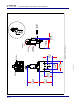
7 Connect the 3.175 mm (1/8 in.) air tube from the "A" port of the solenoid valve
to the air tube on the feedthrough, see Figure 3-1.
NOTE: The air line is 3.175 mm (1/8 in.) as measured on the atmosphere side
of the feedthrough. A user supplied connection from the air supply tube
on the solenoid valve to the air tube on the Cool Drawer sensor is
required.
8 Attach the "P" port of the solenoid valve to a source of air between
55 PSIG (70 PSIA) (3.8 bar) [379 kPa] and 60 PSIG (75 PSIA) (4.1 bar)
[414 kPa], see Figure 3-1.
WARNING
Do not exceed 100 PSIG (115 PSIA) (6.9 bar) [689 kPa].
Connection to excessive pressure may result in personal
injury or equipment damage.
CAUTION
Maximum temperature for the solenoid valve assembly is
105 °C for bakeout and operation.