
Owner manual


1 - 15
PN 074-609-P1A
Cool Drawer Single and Dual Sensors Operating Manual
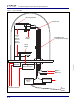
1.6.5 Dual Sensor Drawings
Figure 1-11 displays Standard and Right Angle dual sensor outline drawings which
provide dimensions and other relevant data necessary for planning equipment
configurations.
Figure 1-11 Standard and Right Angle configuration Cool Drawer dual sensors
1.7 Replacement Parts and Accessories
Retainer Assembly with Ceramic Insulator. . . . . . . . . . . . . .PN 123259
Crystal Drawer and Retainer Assembly
(Includes 123259 and 123261). . . . . . . . . . . . . . . . . . . . . . .PN 123260
Crystal Drawer . . . . . . . . . . . . . . . . . . . . . . . . . . . . . . . . . . .PN 123261
1.27
(.50”)
5.08
(2.0”)
.76
(.300”)
1.8
(.71”)
6.35
(2.5”)