
User Manual

3 - 14
IPN 074-289L
Composer Operating Manual
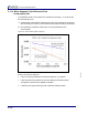
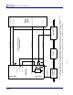
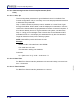
Figure 3-7 . Bulk Flow installation scheme showing optional Bulk Flow Cable’s details. 4.99 megohm resistor is included within the
hood of the mating system I/O connector. Wires are twisted pair; colors as shown; grounds not shown for clarity.
Insure that the grounds from the MFC’s power supplies are maintained or the MFCs may be damaged.
pin 4
pin 6
pins 1,5,7
(0-5 volt analog)
(0-5 volt analog)
brown, grey ground
green, grey ground
(0-24 volt digital)
(0-5 volt analog)
(0-5 volt analog)
pin 21
pin 7
pin 8
pin 10
4.99 M
pin 11
pins 13,14,15,16,17
NO
K4
NC
K5
white, violet ground
red, yellow ground
orange, blue ground
Aux. OUT
Aux. IN
Aux. Gnd
Dil./Conc. Out BNC
Control IN BNC
Control OUT BNC
COMPOSER
System I/O
Option Board
Interconnect Cable
IPN 600-1096-P5, 10, or 20
Composer
Sensor
Bubbler
Source MFC
Control
Input
Flow
Readout
CF Setpoint
CL Control ON/OFF
Concentration Readout
MFC Readback
Reactor
Control
System
Bulk Flow Wire Harness
IPN 600-1149-P1
K4
and
K5
are
toggled
by
firmware
See section 4.3.6 for details