
User Manual

1 - 13
IPN 074-289L
Composer Operating Manual
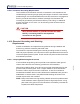
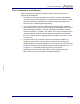
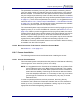
Figure 1-2 Solder Cup Connector
1.10.2.3 How to Connect Electrical Power to the Instrument
All external electrical power is supplied to the Controller through the DB-9 style
POWER connector. It is subsequently distributed to the Transducer through the
Interconnect Cable.
1.10.2.4 Isolated +24 V(dc) Supply
An isolated +24 V(dc) power supply is available to convert line power to a safe
low voltage for the Controller. This optional Power Supply’s output is rated for
a minimum of 60 W. The pin assignments are shown in Table 1-2, below.
Wire Strip
Length 1/4" (6.4 mm)
Contacts
Solder Cup
Grounding
Indents
(Plug Only)
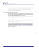
Table 1-2 +24 Volt Power Connector’s Pin Connections
Pin Function
1 Return
2 Return
3 Return
6 +24 Volts
7 +24 Volts
8 +24 Volts
9 Cable Shield