
User Manual


7 - 1
IPN 074-289L
Composer Operating Manual
Chapter 7
External Communications
7.1 Introduction
The Composer supports RS-232C with Checksum.
7.2 Communications Connection
The Instrument System currently supports RS-232C communication only.
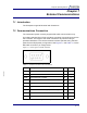
An industry standard 9-pin D-sub-miniature connector is required to connect to
the Controller. The length of the cable is limited to fifty feet according to
published standards. The communications interface operates using the DTE
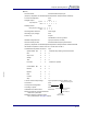
(Data Terminal Equipment) configuration. See Figure 7-1 and Table 7-1 for the
RS-232C connector’s pin assignments.
Figure 7-1 19-Pin Type “D” Female Connector
*Host **IBM compatible computer connector
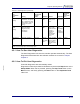
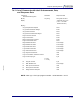
Table 7-1 RS-232C Connector’s Pin Connections
Pin#
Description DB9* DB25**
1 Not Used.
1 -
2 TXD Data transmitted from controller.
2 3
3 RXD Data received by controller.
3 2
4 DSR Not Used.
4 -
5 GND Signal ground.
5 7
6 DTR Output from controller indicating ready for transmit.
6 6
7 CTS Input to controller indicating stop transmitting.
7 4
8 RTS Not used.
8 -
9 GND Shield Ground.
9 -