
User Manual

4 - 28
IPN 074-289L
Composer Operating Manual
and is updated every 200 milliseconds. It is intended for driving a chart recorder
or being read by a system controller or other precision electronic measuring
device. Its normal functionality is tailored by switch settings 1, 2 and 3 on the
CFGR2 switch block as shown in Table 4-6. The Analog option card is
configured at the same time to the same function, only 0-5 volts.
NOTE: If SW#5 of CFGR2 is set, this output is used as a 0-5 V control input to
the Dilution Flow MFC and the settings of SW#1, SW#2 and SW#3 are
ignored in Concentration Control mode.
4.3.6.9 CONTROL OUT Connector
A female BNC connector that outputs a precision analog voltage from 0-5.0 V
into a 2K load that is based on a controller algorithm for maintaining the target
concentration set point. The particular
target concentration used is
coordinated
with the setting of SW#4 on CFGR2. It operates with 15 bit equivalent
resolution, is monotonic to 1 LSB and is updated every 1.1 seconds in
Amplitude Track mode.
4.3.6.10 CONTROL IN Connector
A female BNC connector accepting a precision voltage that is interpreted as the
target set point if SW#4 on CFGR2 is set. Otherwise it is ignored. It is protected
to +/- 35 V continuous. The input voltage is read with a resolution of 14 bits and
an accuracy to 0.01% +/- 1 LSB and an internal linearity of 1 LSB. The A-to-D
converter’s gain drift is +/- 25 PPM/°C maximum and the zero drift is +/- 10
PPM/°C maximum.
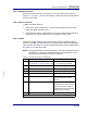
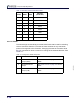
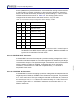
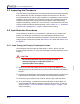
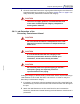
Table 4-6 Concentration Output Configuration Switch Settings, CFGR2
SW#1 SW#2 SW#3 FUNCTION
0 0 0 V
out
= 40[1 - F/F
2
]
0 1 0 0-500 Hz = F-F
2
0 0 1 0-1000 Hz = F-F
2
0 1 1 0-5000 Hz = F-F
2
1 0 0 0 - 0.1% Concentration
1 1 0 0-1% = Concentration
1 0 1 0-10% = Concentration
1 1 1 0-100% = Concentration
Ω