
Instruction Manual

tina46e1-a (2010-03) BPG402.om 19
8
9
1
15
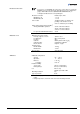
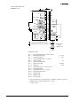
D-Sub,15 pins,
female,
soldering side
Filament status
SP
TxD
RxD
Degas
42 k
Ω
3
4
1
11
9
13
14
7
8
2
12
5
15
1.25 AT
24V
Degas
Ident.
RS232
10
-
-
-
1)
( )
Measuring
signal
-
V
S
6
Threshold value, SP
Common (power GND 24V supply)
Ground (housing, vacuum connection)
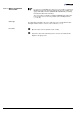
Electrical connection
Pin 1 Relay switching function, common contact
Pin 2 Measuring signal output 0 … +10 V
Pin 3 Threshold (setpoint)
1)
0 … +10 V
Pin 4 Relay switching function, n.o. contact
Pin 5 Supply common 0 V
Pin 6 Not connected internally
Pin 7 Degas (active high) 0 V/+24 V
Pin 8 Supply (V
s
) +24 V
Pin 9 Relay filament status, common contact
2)
Pin 10 Gauge identification
Pin 11 Relay filament status, n.o. contact
2)
Pin 12 Measuring signal common
Pin 13 RS232C, TxD
Pin 14 RS232C, RxD
Pin 15 Do not connect
1)
Do not connect pin 3 for normal operation of the gauge. This pin is reserved for
adjustment of the setpoint potentiometers (→ 38).
2)
→ table on 28.
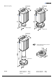
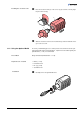
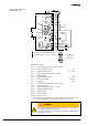
Sensor cable connection
BPG402-S, -SL