
Instruction Manual

tina46e1-a (2010-03) BPG402.om 11
For reasons of compatibility, the expression "sensor cable" is used for all
BPG402 versions in this document, although the pressure reading of the
gauges with fieldbus interface (BPG402-SD and BPG402-SP) is
normally transmitted via the corresponding bus.
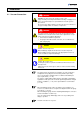
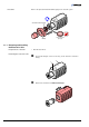
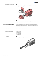
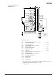
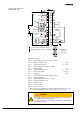
Electrical connection
BPG402-S, -SL
BPG402-SD, -SP
D-Sub,15 pins, male
→ 19
→ 20
Sensor cable shielded, number of conductors de-
pending on the functions used,
max. 15 conductors plus shielding
Cable length (supply voltage 24 VDC
1)
)
Analog and fieldbus operation
For operation with RS232C interface
≤35 m, 0.25 mm²/conductor
≤50 m, 0.34 mm²/conductor
≤100 m, 1.0 mm²/conductor
≤30 m
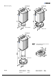
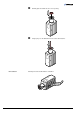
Materials exposed to vacuum
Housing, supports, screens
Feedthroughs
Insulator
Cathode
Cathode holder
Pirani element
stainless steel
NiFe, nickel plated
glass
iridium, yttrium oxide (Y
2
O
3
)
molybdenum, platinum
tungsten, copper
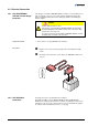
Internal volume
DN 25 ISO-KF
DN 40 CF-R
≈24 cm
3
≈34 cm
3
Pressure max. 2 bar (absolute)
Admissible temperatures
Storage
Operation
Bakeout
Long tube
-20 … 170 °C
0 … 150 °C
+ 80 °C
2)
+150 °C
2)
Relative humidity
Year's mean
During 60 days
≤65 (no condensation)
85% (no condensation)
Use indoors only
altitude up to 2000 m NN
Mounting orientation any
Type of protection IP 30
1)
Measured at gauge connector (consider the voltage drop as function of the sensor cable
length).
2)
Flange temperature, electronics unit removed, horizontally mounted.
Electrical connection
Materials used
Ambiance