
User guide


tira47e1 (2005-08) BPG402SPv1.cp 41
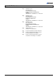
Appendix C: Electrical Connections
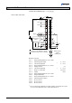
Technical data of BPG402 gauges → [1], [2], [3].
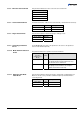
SP A
SP B
SP A
SP B
Degas
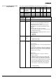
42 kΩ
3
6
1
4
9
11
13
14
7
8
2
12
5
15
1.25 AT
24V
Degas
Ident.
10
-
Threshold-
values
-
-
1)
( )
Common (power GND 24 V supply)
Ground (housing, vacuum connection
+
-
Measuring
signal
-
U
b
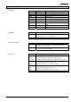
8
9
1
15
D-Sub,15 pins,
female,
soldering side
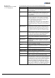
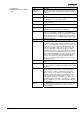
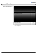
Electrical connection
Pin 1 Relay switching function A, com contact
Pin 2 Measuring signal output 0 … +10 V
Pin 3 Threshold (setpoint) A
1)
0 … +10 V
Pin 4 Relay switching function A, n.o. contact
Pin 5 Supply common 0 V
Pin 6 Threshold (setpoint) B
1)
0 … +10 V
Pin 7 Degas on, active high 0 V/+24 V
Pin 8 Supply +24 V
Pin 9 Relay switching function B, com contact
Pin 10 Gauge identification
Pin 11 Relay switching function B, n.o. contact
Pin 12 Measuring signal common
Pin 13 Do not connect
Pin 14 Do not connect
Pin 15 Do not connect
1)
Do not connect pin 3 and pin 6 for normal operation of the gauge. These pins
are reserved for adjustment of the setpoint potentiometers.
Sensor cable connection