
User Manual


tina03e1-b (2004-02) BPG400 v1.om 45
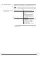
The procedure for setting thresholds is identical for both switching functions.
Put the gauge into operation.
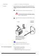
Connect the + lead of a voltmeter to the threshold measurement point of the
selected switching function ("Setpoint A" Pin 3, "Setpoint B" Pin 6) and
its
– lead to Pin 5.
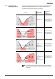
max. ø2.5
Setpoint
A
Pin 3
Setpoint
B
Pin 6
Pin 5
Using a screwdriver (max. ø2.5 mm), set the voltage of the selected
switching function (Setpoint A, B) to the desired value U
Threshold
.
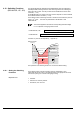
On the BPG400-SR, threshold potentiometer settings ≤0.5 V are
ignored, threshold values defined via RS485 will be effective in-
stead (
→ 42).
Setting of the switching functions is now concluded.
There is no local visual indication of the statuses of the switching func-
tions. However, a functional check of the switching functions (On/Off)
can be made with one of the following methods:
• Reading the status via fieldbus interface → [1] for BPG400-SD,
→ [2] for BPG400-SP, → 41 for BPG400-SR.
• Measurement of the relay contacts at the sensor cable connector
with a ohmmeter/continuity checker (
→ 21).
Procedure