
User Manual


tina03e1-b (2004-02) BPG400 v1.om 31
The built-in RS232C interface allows transmission of digital measurement data and
instrument conditions as well as the setting of instrument parameters.
Caution
Caution: data transmission errors
If the gauge is operated with the RS232C interface and a fieldbus in-
terface at the same time, data transmission errors may occur.
The gauge must not be operated with the RS232C interface and
DeviceNet, Profibus or RS485 at the same time.
The interface works in duplex mode. A nine byte string is sent continuously without
a request approx. every 20 ms.
Commands are transmitted to the gauge in a five byte input (receive) string.
• Data rate
9600 Baud set value, no handshake
• Byte
8 data bits
1 stop bit
• TxD
Pin 13
• RxD
Pin 14
• GND
Pin 5
(Sensor cable connector)
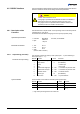
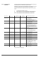
The complete output string (frame) is nine bytes (byte 0 … 8). The data string is
seven bytes (byte 1 … 7).
Byte No Function Value Comment
0 Length of data string 7 (Set value)
1 Page number 5 (For BPG400)
2 Status
→ Status byte
3 Error
→ Error byte
4 Measurement high byte 0 … 255
→ Calculation of pressure value
5 Measurement low byte 0 … 255
→ Calculation of pressure value
6 Software version 0 … 255
→ Software version
7 Sensor type 10 (For BPG400)
8 Check sum 0 … 255
→ Synchronization
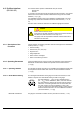
Synchronization of the master is achieved by testing three bytes:
Byte No Function Value Comment
0 Length of data string 7 Set value
1 Page number 5 (For BPG400)
8 Check sum of bytes No 1 … 7 0 … 255 Low byte of check
sum
1)
1)
High order bytes are ignored in the check sum.
4.6 RS232C Interface
4.6.1 Description of the
Functions
Operational parameters
Electrical connections
4.6.1.1 Output String (Transmit
)
Format of the output string
Synchronization