
User Manual

tina03e1-b (2004-02) BPG400 v1.om 25
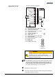
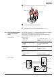
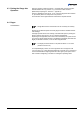
Plug the RS485 (and sensor) cable connector into the gauge.
Sensor cable
RS485 cable
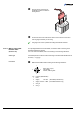
Lock the RS485 (and sensor) cable connector.
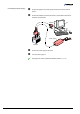
The gauge can now be operated via RS485 interface (→ 37).
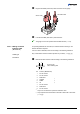
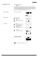
The optional 24 V power supply (→ 52) allows RS232C operation of the BPG400
gauge with any suitable instrument or control device (e.g. PC).
The instrument or control device needs to be equipped with a software that sup-
ports the RS232C protocol of the gauge (
→ 31).
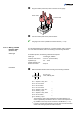
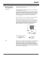
Mains connection
Mains voltage 90 … 250 VAC 50 … 60 Hz
Mains cable 1.8 meter (Schuko DIN and U.S. con-
nectors)
Output (operating voltage of gauge)
Voltage 21 … 27 VDC, set to 24 VDC
Current Max. 1.5 A
Gauge connection
Connector D-Sub, 15 pins, female
24 V cable 5 m, black
Connection of the instrument or control
device
RS232C connection D-Sub, 9 pins, female
Cable 5 m, black, 3 conductors, shielded
13
14
8
15
5
2
3
5
4
6
7
8
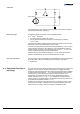
N
PE
L
DC
AC
GND
+24 V
PE
BPG400
D-Sub, 15 pins
RS232C
D-Sub, 9 pins
Mains
90 ... 250 VAC
50 ... 60 Hz
3.2.3 Using the Optional Power
Supply (With RS232C
Line)
Technical data
Wiring diagram