
User Manual

22 tina03e1-b (2004-02) BPG400 v1.om
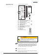
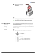
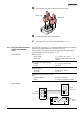
Plug the sensor connector into
the gauge and secure it with the
locking screws.
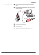
Connect the other end of the sensor cable to the connector of the instru-
ment or gauge controller you are using.
The gauge can now be operated via analog and RS232C interface.
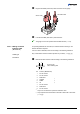
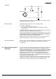
For operating BPG400-SD via DeviceNet, an interface cable conforming to the
DeviceNet standard is required.
If no such cable is available, make one according to the following indications.
A shielded special 5 conductor cable conforming to the DeviceNet standard has to
be used (
→ [4], [6]).
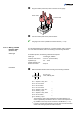
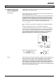
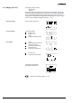
Make the DeviceNet cable according to the following indications.
3
1
42
5
Micro-Style, 5 pins,
(DeviceNet)
female, soldering side
Pin Function (BPG400-SD)
1 Drain
2 Supply +24 VDC (DeviceNet) interface only
3 Supply common GND (DeviceNet interface only)
4 CAN_H
5 CAN_L
3.2.2.2 Making a DeviceNet
Interface Cable
(BPG400-SD)
Cable type
Procedure