Communication Protocol DeviceNet™ Interface for Bayard-Alpert Capacitance Diaphragm Gauge BCG450-SD tira40e1 (2005-04) 1
Intended Use of this Document This Communication protocol contains instructions for operating the vacuum gauges BCG450-SD (featuring DeviceNet interfaces) as slaves together with a DeviceNet master. This manual describes the functionality of DeviceNet for programming purposes. For more information refer to the "DeviceNet specifications" of the Open DeviceNet Vendor Association (ODVA) (→ [2]) and the corresponding european standard (→ [3]).
Contents Intended Use of this Document DeviceNet Interface Abbreviations Trademarks 2 2 2 2 1 Start-Up of the Slave 1.1 Power Supply Requirements 1.2 Front View of the BCG450-SD 1.3 Connectors on the Device 1.4 Side View of the BCG450-SD 1.5 Indicators and Switches 1.5.1 Module Status LED 1.5.2 Network Status LED 1.5.3 Node Address Switch 1.5.4 Data Rate Switch 1.5.5 Setpoint 4 4 4 5 6 6 6 7 7 7 7 2 Object Structure 2.1 Connection Object 2.1.
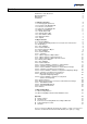
1 Start-Up of the Slave 1.1 Power Supply Requirements The BCG450-SD has to be powered with two voltages: 1.) 2.) 24 Volt DC, 20 W at the 15 pole Sub-D connector for the gauge itself; 24 Volt DC nominal, <2 W range +11 … +25 V) at the DeviceNet micro style connector for the DeviceNet transceiver. 1.
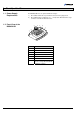
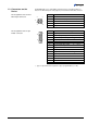
1.3 Connectors on the Device The BCG450-SD uses a "Sealed Micro-Style Connector" for the DeviceNet connection. The DeviceNet part of the gauge is powered via the DeviceNet connector. Pin Assignment of the Sealed Micro-Style Connector Pin 4 3 5 1 Pin Assignment of the 15 pin D-Sub connector 9 1) (2005-04) BCG450SDv1.cp Drain 2 V+ nominal +24 V (range +11 … +25 V) 3 V– 4 CAN_H 5 CAN_L Pin 15 tira40e1 2 8 1 Function 1 Function 1) 1 Relay Setpoint A, n.o.
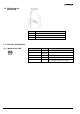
1.4 Side View of the BCG450-SD Position 8 Function Potentiometer for Setpoint A threshold 9 Potentiometer for Setpoint B threshold 10 Special Calibration service / do not use 1.5 Indicators and Switches 1.5.1 Module Status LED Device State Power Off Device Self-Test dark flashing green/red Device Operational green Unrecoverable Fault red Recoverable Fault 6 LED State Description No power applied to device Device is in self-test Device is operating normally.
1.5.2 Network Status LED The network status LED indicates the status of the DeviceNet communication link. State Not Powered/not online Online, not connected Link OK online, connected LED state To indicate dark flashing green green Device is not online. • The device has not completed the Duplicate MAC_ID test yet. • The device may not be powered, look at Module Status LED. Device is online but has no connections in the established state.
2 Object Structure 2.1 Connection Object Class Code 05h = 05d The connection class allocates and manages the internal resources associated with both I/O and explicit messaging connections. The specific instance generated by the connection class is referred to as a connection instance or a connection object. The following Instances of the connection object are supported: • Instance 1: Explicit Messaging • Instance 2: I/O-Polling Please refer to the DeviceNet specification for further information. 2.1.
2.2 Identity Object Class Code 01h = 01d 2.2.1 Class Attributes This object provides identification of and general information about the device. Attribute ID Access Rule Name DeviceNet Description of Attribute Data Type Semantics of Values 1 Get Revision UINT Revision of this object. Note: All class definitions are required to include this class attribute. The current value assigned to this attribute is one (01).
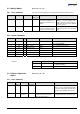
2.3.2 Instance Attributes Attribute ID Access Rule NV/ Name V DeviceNet Data Type Description of Attribute 3 Get NV DeviceType SHORT STRING ASCII Text, "CG" combination gauge 4 Get NV SEMI Standard Revision Level SHORT STRING Specifies the revision level of the SEMI S/A network standard to which the device complies (for example "E54-0997").
Attribute ID Access Rule 14 Get NV/ Name V V DeviceNet Data Type Description of Attribute Exception Detail Warning STRUCT of: A structure of three structures containing a bit mapped representation of the warning detail Common Exception Detail STRUCT of: Size 2 USINT Number of Common Detail Bytes Detail 0 ARRAY of: → "Semantics" section below. Detail 1 BYTE → "Semantics" section below.
Exception Status Exception Status Bit Map Exception Detail Alarm and Exception Detail Warning A single byte attribute whose value indicates the status of the alarms and warnings for the device. The device supports the Expanded Mode. For the Expanded Mode, bit seven of Exception Status attribute is set to one; exceptions are reported through the communication of this Exception Status attribute, formatted as specified in the table below. In addition, the Exception Detail attributes are supported.
Common Exception Detail Attribute Values Bit Common Exception Detail [0] Common Exception Detail [1] 0 0 0 1 0 0 2 EPROM exception 0 3 EEPROM exception power supply input voltage 4 RAM exception 0 5 reserved 0 6 0 0 7 0 0 Common Exception Detail Format Summary Data Component Bit 7 Bit 6 Bit 5 Bit 4 Bit 3 Bit 2 Bit 1 Bit 0 Common Exception Detail Size 0 0 0 0 0 0 1 0 Common Exception Detail 0 0 0 0 Data Memory Nonvolatile Memory Code Memory 0 0 Common Ex
Device Exception Detail Alarms and Manufacturer Exception Detail Alarms Format Data Component Bit 7 Bit 6 Bit 5 Bit 4 Bit 3 Bit 2 Bit 1 Bit 0 0 0 0 0 0 1 1 0 0 0 0 0 0 0 0 Diaphragm Failure 0 0 0 0 0 0 Electronics Failure 0 Device Exception Detail Alarm 0 Pirani 0 0 0 0 0 0 0 0 Device Exception Detail Alarm 1 Pirani 0 0 0 0 0 0 Electronics Failure 0 Device Exception Detail Alarm 2 Hot cathode 0 0 0 0 0 0 0 0 Device Exception Detail Alarm 3 Hot cath
Alarm Enable and Warning Enable 2.3.3 S-Device Supervisor Object States These Boolean attributes are used to enable (1) or disable (0) the S-Device Supervisor object’s process of setting Exception bits. When disabled, corresponding bits are never set; and, if they were set, disabling clears them. Also, alarm and warning states are not retained; when enabled, bits will be set only if the corresponding condition is true. The default state for these Enable attributes is enabled (1).
Service Code 2.3.
Active Value Assemblies or connections may produce this class-level attribute, instead of the Value (Attribute ID 6) of the active S-Analog Sensor instance. The S-Analog Sensor class-level attribute Active Instance Number identifies the object instance that is currently active and providing the Value to the Active Value class-level attribute which is, in turn, produced by the input assemblies that have Active Value as a member.
Attribute ID Access Rule 7 Get 10 Get 25 DeviceNet Data Type Description of Attribute BYTE Alarm and Warning Always zero, because Alarm State of this object and Warning Trip Points are not implemented instance NV Full Scale INT or specified by Data Type The Value of Full Scale for the sensor. Set NV Safe State USINT Specifies the be→ "Semantics" section below.
Value An S-Analog Sensor object instance derives a reading from a physical analog sensor. The reading is converted to the data type and units specified for the Value attribute. Using Counts and INT the following conversion has to be used: Counts = where: Safe State = = = 12.5 12.624903 10.5 This attribute specifies what value will be held in Value for states other than Executing.
2.4.2.3 Instance Attributes of Instance 2 / Hot Cathode Ion Gauge Attribute ID Access Rule 3 Set/Cond. → below 4 NV Data Units ENGUNITS → "Semantics" 20 NV/ V Name Following is the Instance 2 with the subclass extension of the hot cathode ion gauge part of the BCG450-SD. This instance is used to provide control and status information for the hot cathode ion gauge part of the BCG450-SD.
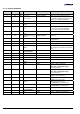
Attribute ID Access Rule NV/ V Name DeviceNet Data Type Description of Attribute Semantics of Values 96 Get V Status Extension BYTE Bit mapped byte providing additional status bits Bit description: 0 Reading Invalid (Logical Inversion of Reading Valid) 1 Overrange Exceeded 2 Underrange Exceeded 99 Get NV Subclass UINT Identifies the subset of additional attributes, services and behaviors for hot cathode ion gauges 5 100 Get NV State Emission Control Mode USINT Represents the state
Status Extension Data Component Sensor Alarm Byte 0 22 8 Bits providing the current sensor alarm state of the instance Bit 7 Bit 6 Bit 5 Bit 4 Bit 3 Bit 2 Bit 1 Bit 0 0 0 0 0 0 Underrange Exceeded Overrange Exceeded Reading Invalid tira40e1 (2005-04) BCG450SDv1.
2.4.2.5 Instance Attributes of Instance 3 / Capacitance Diaphragm Gauge Attribute ID Access Rule 3 Set/Cond. → below 4 NV Data Units ENGUNITS → "Semantics" tira40e1 NV/ V Name Following is the Instance 3 with the subclass extension of the capacitance diaphragm gauge part of the BCG450-SD. This instance is used to provide control and status information for the capacitance diaphragm gauge part of the BCG450-SD.
2.4.2.6 Semantics of S-Analog Sensor Instance 3 Data Type → Instance 1 Value An S-Analog Sensor object instance derives a reading from a physical analog sensor. The reading is converted to the data type and units specified for the Value attribute. Using Counts and INT the following conversion has to be used: Counts = where: kmbar kTorr kPa [ log10 (pressure) + k ] × 2000 = = = 12.5 12.624903 10.5 Safe State → Instance 1 Safe Value → Instance 1 Sensor Alarm 16 Bits are used as sensor faults.
2.4.2.7 Object-Specific Services on Instance 3 / Capacitance Diaphragm Gauge USER ATM Adjust Service Code 32h Service Name Description of Service User Atmosphere Adjust Performs an Atmosphere Adjust Piezo to Capacitance Diaphragm Gauge User ATM Adjust Service Data Field Parameters: Parameter User ATM Adjust Datatype BOOL 0 = Unlock user ATM Adjust 1 = executes an User ATM Adjust and lock There are no state transitions associated with the invocation of this service.
2.4.2.8 Instance Attributes of Instance 21 / Setpoint A (Instance 22 / Setpoint B) Attribute ID Access Rule NV/V Name DeviceNet Data Type Description of Attribute 3 Set / Conditional: → Instance 1 NV 4 Get NV 5 Get 6 7 Data Type USINT Determines the Data Type → "Semantics" section below. of Value and all related int C3h [default] attributes as specified in float CAh this table. Data Units UINT Determines the Units context of Value and all related attributes.
Status A bit mapped byte which indicates the Alarm and Warning Exception status of the object instance.
Setpoint function "Atmosphere Control" The setpoint function "Atmosphere Control" is used to decide whether the measured pressure is within a specified percentage of the atmospheric pressure (→ diagram below). Attribute 101 "Percentage of Atmosphere" is used to define the percentage of atmospheric pressure. If the measured pressure is within this window, the corresponding relay will be activated (→ [4]). A fixed hysteresis of 2% of the atmospheric pressure threshold is programmed.
2.4.3 Common Services The S-Analog Sensor Object provides the following Common Services: Service Service Name Code Description of Service 0Eh Get_Attribute_Single Returns the contents of the specified attribute. 10h Set_Attribute_Single Modifies an attribute value. 2.4.4 Object-Specific Services on Instance 2 / Hot Cathode Ion Gauge 2.4.4.
2.4.4.3 Emission Control Mode Set Emission Control Mode Data Field Emission User Modes Service Code Service Name Description of Service 32h Set Emission Control Mode • Automatic The Emission is switched on and off by the Pirani automatically.
3 I/O Assembly Object Class Code 04h A collection of assembly objects allows the sending of attributes from different application objects in one message (i.e. Polling I/O). 3.1 I/O Assembly Instances tira40e1 (2005-04) BCG450SDv1.cp The following table identifies the I/O assembly instances supported by the gauge device.
3.2 I/O Assembly Object Instance Data Attribute Format In order to maintain consistency, this device type will only allow connections to either INT or REAL based Assembly instances (→ Data Type definition 18). Once a valid connection is established, attempts to configure connections to a different type of Assembly instance will return an error.
Appendix A: Range of Values B: Specific Codes C: Conversion of a Floating Number According to IEEE 754 Integer int –32767 … 32768 Unsigned integer uint Float float 0 … 65535 according IEEE 754 Manufacturer product code 13 = BCG450-SD General Number received AA BB CC DDh 1. Reverse the sequence of the HEX words 2.
Example Number received 00 00 CA 42h 1. Convert sequence of the HEX words 2. Separate into bytes 42h CAh 00h 00h 0100 0010b 1 1 0 0 1010b 0000 0000b 0000 0000b Sign 3. Calculate (4-Byte, floating format) 8-Bit exponent 23-Bit mantissa 0 1000 0101b 100 1010 0000 0000 0000 0000b Ø Ø Ø -10 ⎛ 100 1010 0000 0000 0000 0000 ⎞ b⎟ 1+ ⎜⎜ ⎟⎟ 23 ⎜ 2 ⎝ ⎠ ⎛ 4849664 d ⎞ ⎟ ⎝ 8388608 d ⎠ = 1+ ⎜ Ø Ø Sign = Exponent = Mantissa = 1 133 1.
Example of the principal allocation process. Master MAC ID....0 Allocation choice: Explicit, Poll, bit strobe, COS Slave address: 2 Allocated instances may not be valid for the BCG450-SD ⇒ Allocation String: Slave’s explicit/unconnected response message: 416 413 00 4B 03 01 57 00 00 CB 00 Within the first allocation message the explicit connection has to be established. The I/O connections bit strobe and COS/Cyclic are not supported by the BCG450-SD.
Setting of assemblies If you want to set the number of the chosen assembly, you have to set the attributes 14 and 16 in the corresponding instance of the connection object. To set this value, the connection has to be allocated, but the EPR attribute has not to be set to any value. Examples • Read a configured assembly (addresses as specified above): Get single request: ID Message Body 414 00 0E 05 02 0E get produced connection path (Request for input assembly by master).
E: tira40e1 Literature (2005-04) BCG450SDv1.cp [1] www.inficon.com Product descriptions and downloads INFICON AG, LI–9496 Balzers, Liechtenstein [2] www.odva.org Open DeviceNet Vendor Association, Inc. DeviceNet™ Specifications [3] European Standard for DeviceNet EN 50325 [4] www.inficon.com Operating Instructions BCG450, BCG450-SD, BCG450-SP tina40d1 / tina40e1 INFICON AG, LI–9496 Balzers, Liechtenstein [5] www.inficon.
Notes 38 tira40e1 (2005-04) BCG450SDv1.
Notes tira40e1 (2005-04) BCG450SDv1.
LI–9496 Balzers Liechtenstein Tel +423 / 388 3111 Fax +423 / 388 3700 reachus@inficon.com t i r a40e1 www.inficon.