
Owner's manual


tina40e1-b (2011-04) 9
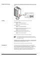
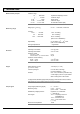
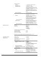
Display panel
Background illumination
Dimensions
Pressure units (pressure p)
LCD matrix, 32×16 pixels
two colors red/green
16.0 mm × 11.2 mm
mbar (default), Torr, Pa
(selecting the pressure unit → 33)
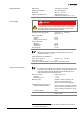
DANGER
The gauge may only be connected to power supplies, instruments or
control devices that conform to the requirements of a grounded extra-
low voltage (SELV). The connection to the gauge has to be fused
(INFICON controllers fulfill these requirements).
Operating voltage at the gauge +24 VDC (+20 … +28 VDC)
1)
ripple max. 2 V
pp
Power consumption
Standard
Degas
Emission start (<200 ms)
≤0.5 A
≤0.9 A
≤1.4 A
Power consumption
BCG450
BCG450-SD
BCG450-SP
≤18 W
≤20 W
≤20 W
Fuse necessary 1.25 AT
BCG450-SD requires an additional, separate power supply for the
DeviceNet interface (→ 21).
Supply voltage at the DeviceNet con-
nector, (Pin 2 and Pin 3)
+24 VDC (+11 … +25 VDC)
Power consumption <2 W
The gauge is protected against reversed polarity of the supply voltage.
For reasons of compatibility, the expression "sensor cable" is used for all
BCG450 versions in this document, although the pressure reading of the
gauges with fieldbus interface (BCG450-SD and BCG450-SP) is nor-
mally transmitted via the corresponding bus.
Electrical connector
BCG450
BCG450-SD, -SP
D-Sub,15-pin, male
→ 19
→ 20
Measuring cable shielded, number of conductors de-
pending on the functions used
(max. 15 conductors plus shielding)
Cable length (supply voltage 24 V
1)
)
Analog and fieldbus operation
RS232C operation
≤35 m, conductor cross-section 0.25 mm²
≤50 m, conductor cross-section 0.34 mm²
≤100 m, conductor cross-section 1.0 mm²
≤30 m
Gauge identification
42 kΩ resistor between Pin 10 and Pin 5
(sensor cable)
1)
Measured at sensor cable connector (consider the voltage drop as function of
the sensor cable length).
Display (BCG450)
Power supply
Sensor cable connection