
Owner's manual


42
tina40e1-b (2011-04)
The procedure for setting thresholds is identical for both switching functions.
Put the gauge into operation.
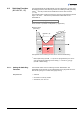
Connect the + lead of a voltmeter to the threshold measurement point of the
selected switching function ("Setpoint A" Pin 3, "Setpoint B" Pin 6) and
its – lead to a ground contact nearby (eg. grounded locking screw nut of
connector or vacuum connection of the gauge).
The threshold voltages are referenced to ground (housing,
vacuum connection), not to Pin 5 (common power GND 24 V
supply).
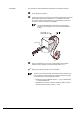
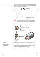
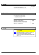
max. ø2.5
Setpoint
A
Pin 3
Setpoint
B
Pin 6
( )
Using a screwdriver (max. ø2.5 mm), set the voltage of the selected
switching function (Setpoint A, B) to the desired value U
Threshold
.
Setting of the switching functions is now concluded.
There is no local visual indication of the statuses of the switching func-
tions. However, a functional check of the switching functions (On/Off)
can be made with one of the following methods:
• Reading the status via fieldbus interface → [1] for BCG450-SD,
→ [2] for BCG450-SP.
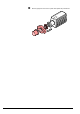
• Measurement of the relay contacts at the sensor cable connector
with a ohmmeter/continuity checker (→ 20).
Procedure