
Owner's manual

20
tina40e1-b (2011-04)
SP A
SP B
SP A
2)
SP B
2)
Degas
42 k
Ω
3
6
1
4
9
11
13
14
7
8
2
12
5
15
1.25 AT
24V
Degas
Ident.
10
-
-
-
1)
( )
+
-
Measuring
signal
-
8
9
1
15
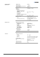
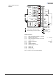
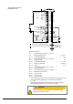
D-Sub,15-pin,
female,
soldering side
Common (power GND 24V supply)
Ground (housing, vacuum connection)
Threshold values
Electrical connection
Pin 1 Relay switching function A, n.o. contact
2)
Pin 2 Measuring signal output 0 … +10.13 V
Pin 3 Threshold (setpoint) A
1)
0 … +10 V
Pin 4 Relay switching function A, com contact
2)
Pin 5 Supply common 0 V
Pin 6 Threshold (setpoint) B
1)
0 … +10 V
Pin 7 Degas on, active high 0 V/+24 V
Pin 8 Supply +24 V
Pin 9 Relay switching function B, n.o. contact
2)
Pin 10 Gauge identification
Pin 11 Relay switching function B, com contact
2)
Pin 12 Measuring signal common
Pin 13 Do not connect
Pin 14 Do not connect
Pin 15 Do not connect
1)
Do not connect pin 3 and pin 6 for normal operation of the gauge. These
pins are reserved for adjustment of the setpoint potentiometers
(→ 42).
2)
Relay assignement can be reprogrammed for atmosphere switching
function via serial interfaces (→ 31 and [1] or [2]).
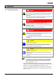
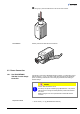
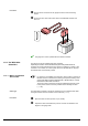
WARNING
Incorrect connection, incorrect polarity or inadmissible supply
voltages can damage the gauge.
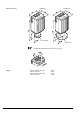
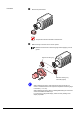
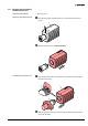
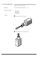
Sensor cable connection
BCG450-SD, -SP