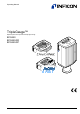
Operating Manual TripleGauge™ Bayard-Alpert Pirani Capacitance Diaphragm Gauge BCG450 BCG450-SD BCG450-SP tina40e1-b (2011-04) 1
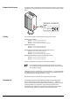
Product Identification In all communications with INFICON, please specify the information on the product nameplate. For convenient reference copy that information into the space provided below.
Functional Principle Due to the combination of three sensor technologies incorporated in the gauge (Capacitance diaphragm sensor, Pirani sensor and hot cathode ionisation sensor (BA)), a minimized gas type dependence is achieved. Between 10 mbar and atmospheric pressure, the capacitance diaphragm sensor operates without any gas type dependence. Below 1 mbar, the Pirani sensor and the hot cathode ionisation sensor take over with only a small gas type dependence.
Contents 4 Product Identification Validity Intended Use Functional Principle Trademarks 2 2 2 3 3 1 Safety 1.1 Symbols Used 1.2 Personnel Qualifications 1.3 General Safety Instructions 1.4 Liability and Warranty 6 6 6 7 7 2 Technical Data 8 3 Installation 3.1 Vacuum Connection 3.1.1 Removing and Installing the Electronics Unit 3.1.2 Using the Optional Baffle 3.2 Power Connection 3.2.1 Use With INFICON VGC40x Vacuum Gauge Controller 3.2.2 Use With Other Controllers 3.2.2.
6 Maintenance, Repair 6.1 Maintenance 6.1.1 Cleaning the Gauge 6.2 Adjusting the Gauge 6.3 Adjusting the Atmosphere Sensor 6.4 What to Do in Case of Problems 6.
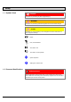
1 Safety 1.1 Symbols Used DANGER Information on preventing any kind of physical injury. WARNING Information on preventing extensive equipment and environmental damage. Caution Information on correct handling or use. Disregard can lead to malfunctions or minor equipment damage. Notice Hint, recommendation The result is O.K. The result is not as expected. Optical inspection Waiting time, reaction time 1.
1.3 General Safety Instructions • Adhere to the applicable regulations and take the necessary precautions for the process media used. Consider possible reactions between the materials (→ 11) and the process media. Consider possible reactions of the process media (e.g. explosion) due to the heat generated by the product. • Adhere to the applicable regulations and take the necessary precautions for all work you are going to do and consider the safety instructions in this document.
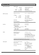
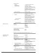
2 Technical Data Measurement principle Measuring range Pressure range 10 … 1500 mbar 1 … 10 mbar -2 1 mbar 2×10 … -3 -2 5×10 … 2×10 mbar -10 … 5×10⁻³ mbar 5×10 capacitance diaphragm sensor crossover range Pirani sensor crossover range hot cathode ionisation (BA) Range (air, O2, CO, N2) 5×10⁻¹⁰ … 1500 mbar, continuous Accuracy -8 50 mbar 1×10 … 50 … 950 mbar 950 … 1050 mbar Repeatability Gas type dependence Emission Degas ±15% of reading ±5% of reading ±2.5% of reading (after 10 min.
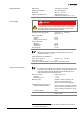
Display (BCG450) Display panel LCD matrix, 32×16 pixels Background illumination Dimensions Pressure units (pressure p) two colors red/green 16.0 mm × 11.2 mm mbar (default), Torr, Pa (selecting the pressure unit → Power supply 33) DANGER The gauge may only be connected to power supplies, instruments or control devices that conform to the requirements of a grounded extralow voltage (SELV). The connection to the gauge has to be fused (INFICON controllers fulfill these requirements).
Switching functions BCG450 BCG450-SD, -SP Adjustment range Relay contact rating Atmosphere switching function BCG450 Relay contact rating BCG450-SD/SP Relay contact rating RS232C interface Data rate Data format Connections (sensor cable connector) TxD (Transmit Data) RxD (Receive Data) Supply common (GND) → Atmosphere switching function 2 (setpoints A and B) -9 1×10 mbar … 100 mbar Setpoints adjustable via potentiometers, one floating, normally open relay contact per setpoint (→ 20, 41) (Adjusting t
Profibus interface (BCG450-SP) Fieldbus name Standard applied Communication protocol data format → [9], [7] RS485 Data rate ≤12 MBaud (→ Node address Local (Adjustable via hexadecimal "ADDRESS", "MSD", "LSD" switches) Default setting Via Profibus (hexadecimal "ADDRESS" switches set to >7dhex (>125dec)) 00 … 7Dhex (0 … 125dec) 5Chex Cable length, system wiring Materials exposed to vacuum Housing, supports, screens Feedthroughs Insulator Cathode Cathode holder Pirani element Sensor diaphragm Sensor co
Dimensions [mm] 4-40UNC 2B 4-40UNC 2B DN 25 ISO-KF DN 40 CF-R Gauges with DeviceNet connector are 14 mm longer.
3 Installation 3.1 Vacuum Connection DANGER DANGER: overpressure in the vacuum system >1 bar Injury caused by released parts and harm caused by escaping process gases can result if clamps are opened while the vacuum system is pressurized. Do not open any clamps while the vacuum system is pressurized. Use the type of clamps which are suited to overpressure. DANGER DANGER: overpressure in the vacuum system >2.5 bar KF flange connections with elastomer seals (e.g. O-rings) cannot withstand such pressures.
Procedure Remove the protective lid. The protective lid will be needed for maintenance.. Make the flange connection to the vacuum system INFICON recommends to install the gauge without applying vacuum grease. Seal with centering ring or Seal with centering ring and baffle (Option) When installing the gauge, make sure that the area around the connector is accessible for the tools required for adjustment while the gauge is mounted (→ 41, 45).
3.1.1 Removing and Installing the Electronics Unit Required tools/material • Allen key, AF 2.5 Removing the electronics unit Unscrew the hexagon socket set screw (1) on the side of the electronics unit (2). 2 1 Remove the electronics unit without twisting it. Installing the electronics unit Place the electronics unit (2) on the sensor (3) (be careful to correctly align the pins and notch (4)). 4 2 3 Slide the electronics unit in to the mechanical stop and lock it with the hexagon socket set screw.
3.1.2 Using the Optional Baffle Requirement Required tools / material In severely contaminating processes and to protect measurement electrodes optically against light and fast charged particles, replacement of the built-in grid by the optional baffle (→ 50) is recommended. The gauge is deinstalled (deinstallation gauge → • Baffle (→ • Pointed tweezers • Pin (e.g. pencil) • Screwdriver No 1 43). 50) Installation Carefully remove the grid with tweezers.
Using a pin, press the baffle down in the center until it catches. Deinstallation Carefully remove the baffle with the screwdriver. 3.2 Power Connection 3.2.1 Use With INFICON VGC40x Vacuum Gauge Controller If the gauge is used with an INFICON VGC40x controller, a corresponding sensor cable is required (→ [3]). The sensor cable permits supplying the gauge with power, transmitting measurement values and gauge statuses, and making parameter settings.
Procedure Plug the sensor connector into the gauge and secure it with the locking screws. Connect the other end of the sensor cable to the INFICON controller and secure it. The gauge can now be operated with the VGC40x controller. 3.2.2 Use With Other Controllers 3.2.2.1 Making an Individual Sensor Cable Cable type The gauge can also be operated with other controllers.
Sensor cable connection BCG450 Atmospheric pressure reached 4 TxD 13 1 RS232 RxD 14 Degas 7 Measuring signal - Degas 2 - 12 + 1.25 AT 42 kΩ 8 Ident. 10 5 15 Common (power GND 24V supply) 9 1 15 8 Ground (housing, vacuum connection) - - 24V D-Sub,15-pin, female, soldering side Electrical connection Pin 1 Pin 2 Pin 4 Pin 5 Pin 7 Pin 8 Pin 10 Pin 12 Pin 13 Pin 14 Pin 15 Relay "Atmosphere reached", n.o.
Sensor cable connection BCG450-SD, -SP ( - ) 1) SP A Threshold values SP B 3 6 1 SP A 2) 4 9 SP B 2) 11 13 14 Degas 7 Measuring signal - Degas 2 - 12 + 1.25 AT 42 kΩ 8 10 Ident. 5 15 Common (power GND 24V supply) 9 1 Ground (housing, vacuum connection) 15 8 - - 24V D-Sub,15-pin, female, soldering side Electrical connection 2) Pin 1 Relay switching function A, n.o. contact Pin 2 Measuring signal output 0 … +10.
For cable lengths up to 5 m (0.34 mm2 conductor cross-section) the output signal can be measured directly between the positive signal output (Pin 2) and supply common GND (Pin 5). At greater cable lengths, differential measurement between signal output (Pin 2) and signal common (Pin 12) is recommended. Reassemble the cable connector. On the other cable end, terminate the cable according to the requirements of the gauge controller you are using.
Plug the DeviceNet (and sensor) cable connector into the gauge. DeviceNet cable Sensor cable Lock the DeviceNet (and sensor) cable connector. The gauge can now be operated via DeviceNet interface (→ 3.2.2.3 Making a Profibus Interface Cable (BCG450-SP) Cable type 38). For operating BCG450-SP via Profibus, an interface cable conforming to the Profibus standard is required. If no such cable is available, make one according to the following indications.
Plug the Profibus (and sensor) cable connector into the gauge. Sensor cable Profibus cable Lock the Profibus (and sensor) cable connector. The gauge can now be operated via Profibus interface (→ 3.2.3 Using the Optional Power Supply (With RS232C Line) Technical data tina40e1-b (2011-04) 40). The optional 24 V power supply (→ 50) allows RS232C operation of the BCG450 gauge with any suitable instrument or control device.
Wiring diagram 8 7 6 4 BCG450 D-Sub, 15-pin 5 5 13 2 14 3 RS232C D-Sub, 9-pin 8 15 +24 V L DC GND N AC PE Mains 90 ... 250 VAC 50 ... 60 Hz PE Connecting the power supply Connect the power supply to the the gauge and lock the connector with the screws. Connect the RS232C line to the instrument or control device and lock the connector with the screws. RS232C PC Mains Power supply BCG450 Connect the power supply to the mains. The gauge can now be operated via RS232C interface (→ 24 33).
4 Operation 4.1 Measuring Principle, Measuring Behavior Bayard-Alpert (BA) The BCG450 vacuum gauges consist of three separate measuring systems (hot cathode Bayard-Alpert (BA) Pirani sensor and capacitance diaphragm sensor). The BA measuring system uses an electrode system according to Bayard-Alpert which is designed for a low x-ray limit. The measuring principle of this measuring system is based on gas ionization.
Schematic Vb Pirani sensor The bridge voltage Vm is a measure for the gas pressure and is further processed electronically (linearization, conversion). Capacitance diaphragm sensorr A capacitance diaphragm sensor consists of a reference vacuum chamber, separated from the measured gas pressure by a diaphragm. The capacitance of a pair of electrodes attached to the diaphragm and the chamber is measured electronically.
Gas type dependence Due to the capacitance diaphragm sensor used in the upper pressure range, a minimized gas type dependence is achieved. Pressure range 10 … 1500 mbar 1 … 10 mbar 2×10⁻² … 1 mbar 1) 4.
4.3 Putting the Gauge Into Operation When the operating voltage is supplied (→ Technical Data), the output signal is available between Pin 2 (+) and Pin 12 (–) of the sensor cable connector (Relationship Output Signal – Pressure → Appendix A). Allow for a stabilizing time of approx. 10 min. Once the gauge has been switched on, permanently leave it on irrespective of the pressure. Communication via the digital interfaces is described in separate sections of this document. 4.
4.5 Emission Control Mode General The emission control mode function defines the rules by which the emission of the gauge is switched on and off. The manual mode feature has a positive effect on gauge live time, mainly in process situations where the process chamber has to be vented frequently. Emission Control Mode Description • Automatic (AUTO) By default, the automatic mode is active and the emission is switched on and off automatically by the gauge.
4.6 Atmosphere Switching Function 4.6.1 Functional Principle The Atmosphere Switching Function is used to define an atmospheric pressure threshold where a (semiconductor) relay "Atmospheric pressure reached" is activated or deactivated 1). The atmospheric pressure threshold is user programmable as a percentage of the 2) ambient atmospheric pressure (100%) . A separate sensor built into the gauge (measuring ambient atmospheric pressure ) is used as a reference.
Example The following diagram shows the functional principle using example values (italic = example values): Measuring signal (Pressure p) Upper limit of measuring range of gauge 1500 mbar Atmospheric pressure (100%, ambient) 2) e alu dv e r su Atmospheric pressure ea threshold (85%) M 980 mbar 833 mbar 816 mbar Hysteresis (2% of atmospheric pressure threshold) Relay status "Atmospheric pressure reached" 4.6.
4.6.3 Wiring the relay "Atmospheric Pressure Reached" (BCG450) The signal: atmospheric pressure reached is made available via a floating n. o. 1) contact of a photo MOS relay contact at the sensor cable connector (→ 19) . Specifications of the n. o. contact: Load voltage (VL) Load current ≤30 V AC/DC ≤300 mA AC/DC 2) Atmospheric pressure reached 1 4 Sensor cable connector UL RV 2) CL 2) Load Diode 4.
Error Display No error (green background illumination) Pirani sensor error (red background illumination) BA sensor error (red background illumination) Diaphragm sensor error (red background illumination) EEPROM error (red background illumination) Internal data connection failure (red background illumination) What to do in case of problems → 4.8 RS232C Interface 47.
4.8.1 Description of the Functions Operational parameters Electrical connections 4.8.1.1 Output String (Transmit) Format of the output string The interface works in duplex mode. A nine byte string is sent continuously without a request approx. every 20 ms. Commands are transmitted to the gauge in a five byte input (receive) string.
Status byte Bit 1 Bit 0 0 0 0 1 1 1 0 1 Bit 2 reserved for future use reserved for future use Bit 3 Definition toggle bit, changes with every string received correctly 0⇔1 Bit 5 Bit 4 0 0 1 0 1 0 Bit 7 Bit 6 x x Bit No.
Example The example is based on the following output string: Byte No. 0 1 2 3 4 5 6 7 8 Value 7 5 0 0 242 48 20 13 69 The instrument or controller (receiver) interprets this string as follows: Byte No. Function 0 1 2 3 4 5 6 7 8 4.8.1.
Admissible input strings For commands to the gauge, six defined strings are used: Command: 1) Set the unit mbar on the display Set the unit Torr on the display 1) Set the unit Pa on the display 1) Storage of current unit 3) Switch degas on (switches itself off after 3 min.) Switch degas off (before 3 min.
4.9 DeviceNet Interface (BCG450-SD) This interface allows operation of BCG450-SD with part number 353-557, 353-558 and 353-562 in connection with other devices that are suited for DeviceNet operation. The physical interface and communication firmware of BCG450-SD comply with the DeviceNet standard (→ [4], [6]). Two adjustable switching functions are integrated in BCG450-SD. The corresponding relay contacts are available at the sensor cable connector (→ 8, 20, 41).
4.9.2.3 Data Rate Setting The admissible data rate depends on a number of factors such as system parameters and cable length → [4], [6]). It can be set on the gauge or programmed via DeviceNet. By means of the "RATE" switch, the data rate can be set to 125 ("1"), 250 ("2") or 500 kBaud ("5"). If the switch is in any of the "P" positions, the data rate is programmable via DeviceNet (→ [1]). 4.9.
4.10 Profibus Interface (BCG450-SP) This interface allows operation of BCG450-SP with part number 353-554 and 353-556 in connection with other devices that are suited for Profibus operation. The physical interface and communication firmware of BCG450-SP comply with the Profibus standard (→ [7], [5]. Two adjustable switching functions are integrated in the BCG450-SP. The corresponding relay contacts are available at the sensor cable connector (→ 8, 20, 41).
4.11 Switching Functions (BCG450-SD, -SP) The gauges BCG450-SD and BCG450-SP have two independent, manually settable switching functions. Each switching function has a floating normally open relay contact 1). The relay contacts are accessible at the sensor cable connector (→ 20). The threshold values of switching functions A and B can be set within the pressure -9 range 1×10 mbar … 1000 mbar via potentiometers "SETPOINT A" and "SETPOINT B". UThreshold = 0.75 × (log pSetpoint – c) + 7.
Procedure The procedure for setting thresholds is identical for both switching functions. Put the gauge into operation. Connect the + lead of a voltmeter to the threshold measurement point of the selected switching function ("Setpoint A" Pin 3, "Setpoint B" Pin 6) and its – lead to a ground contact nearby (eg. grounded locking screw nut of connector or vacuum connection of the gauge). The threshold voltages are referenced to ground (housing, vacuum connection), not to Pin 5 (common power GND 24 V supply).
5 Deinstallation DANGER DANGER: contaminated parts Contaminated parts can be detrimental to health and environment. Before beginning to work, find out whether any parts are contaminated. Adhere to the relevant regulations and take the necessary precautions when handling contaminated parts. Caution Caution: vacuum component Dirt and damages impair the function of the vacuum component. When handling vacuum components, take appropriate measures to ensure cleanliness and prevent damages.
Remove gauge from the vacuum system and replace the protective lid.
6 Maintenance, Repair 6.1 Maintenance DANGER DANGER: contaminated parts Contaminated parts can be detrimental to health and environment. Before beginning to work, find out whether any parts are contaminated. Adhere to the relevant regulations and take the necessary precautions when handling contaminated parts. 6.1.1 Cleaning the Gauge Small deposits on the electrode system can be removed by baking the anode (Degas → 28). In the case of severe contamination, the baffle can be exchanged easily (→ 16).
Two 5 byte long command strings have to be sent to the gauge in succession (general RS232 information → 33): String No. 1 (Unlock atmosphere sensor adjustment): Byte No. Function 0 1 2 3 4 Length of data string Data Data Data Check sum (of bytes No. 1 … 3) Value 0x03 0x10 0x1C 0x00 0x2C Comment hex set value hex hex hex hex low byte of sum, high byte is ignored String No. 2 (execute sensor adjustment): Byte No. Function 0 1 2 3 4 Length of data string Data Data Data Check sum (of bytes No.
6.4 What to Do in Case of Problems Required tools / material Troubleshooting (BCG450) In the event of a fault or a complete failure of the output signal, the gauge can easily be checked. • Voltmeter / ohmmeter • Allen key, AF 2.5 • Spare sensor (if the sensor is faulty) The output signal is available at the sensor cable connector (Pin 2 and Pin 12). In case of an error, it may be helpful to just turn off the mains supply and turn it on again after 5 s.
Troubleshooting (sensor) If the cause of a fault is suspected to be in the sensor, the following checks can be made with an ohmmeter (the vacuum system need not be vented for this purpose). Separate the sensor from the electronics unit (→ the following measurements on the contact pins. Ohmmeter measurement between pins Possible cause 2+4 ≈37 Ω 4+5 15). Using an ohmmeter, make >>37 Ω Pirani element 1 broken >>37 Ω Pirani element 2 broken ≈37 Ω ≈0.15 Ω >>0.
6.5 Replacing the Sensor Required tools / material Replacement is necessary, when • the sensor is severely contaminated • the sensor is mechanically deformed • the sensor is faulty, e.g. filament of hot cathode broken (→ • the sensor is faulty, e.g. Pirani element broken (→ • Allen key, AF 2.5 • Spare sensor (→ 47) 47) 50) Procedure Deinstall the gauge (→ 43). Deinstall the electronics unit from the faulty sensor and mount it to the new sensor (→ 15).
7 Options Part number 24 VDC power supply / RS232C line (→ 23) Baffle DN 25 ISO-KF / DN 40 CF-R (→ 16) Seal with centering ring and baffle DN 25 ISO-KF 353-511 353-512 211-113 8 Spare Parts When ordering spare parts, always indicate: • All information on the product nameplate • Description and part number Part number Replacement sensor BCG450, vacuum connection DN 25 ISO-KF (including allen key) Replacement sensor BCG450, vacuum connection DN 25 ISO-KF with baffle (including allen key) Replacement s
10 Returning the Product WARNING WARNING: forwarding contaminated products Contaminated products (e.g. radioactive, toxic, caustic or biological hazard) can be detrimental to health and environment. Products returned to INFICON should preferably be free of harmful substances. Adhere to the forwarding regulations of all involved countries and forwarding companies and enclose a duly completed declaration of contamination (→ 56).
Appendix A: Relationship Measuring Signal – Pressure p = 10(U - 7.75) / 0.75 + c Conversion formulae U = 0.75 × (log p - c) + 7.75 where Conversion curve U p c [V] [V] [V] [mbar] [Pa] [Torr] 0 2 -0.125 Pressure p [mbar] 1E+04 1E+03 1E+02 1E+01 1E–03 1E–04 1E–05 Inadmissible range 1E–02 Sensor error 1E–01 Inadmissible range 1E+00 1E–06 1E–07 1E–08 1E–09 1E–10 0.0 1.0 2.0 3.0 4.0 5.0 6.0 7.0 8.0 9.0 10.0 Measuring signal U[V] Conversion table Output signal U [V] [mbar] 0.
B: Gas Type Dependence Indication range above 10-2 mbar Pressure indicated (gauge adjusted for air) p [mbar] 4 2 103 Crossover range Pirani sensor 8 6 4 Capacitance diaphragm sensor 2 102 8 6 4 2 101 8 6 4 2 100 8 6 4 2 Air, O2, CO, N2 10–1 8 6 4 He Ar 2 10–2 8 6 4 2 10–3 8 6 4 2 10–4 10–4 2 4 6 10–3 2 4 6 10–2 2 4 6 10–1 2 4 6 100 2 4 6 101 2 4 6 102 2 4 6 103 2 peff [mbar] tina40e1-b (2011-04) 53
Calibration in pressure range 10-2 … 1 mbar The gas type dependence in the pressure range 10-2 … 1 mbar (Pirani sensor range) can be compensated by means of the following formula: peff = C × indicated pressure where Gas type Calibration factor He Ne Ar Kr Xe H2 Air, O2, CO, N2 CO2 Water vapor Freon 12 0.8 1.4 1.7 2.4 3 0.5 1 0.9 0.5 0.7 (The above calibration factors are mean values.
C: tina40e1-b Literature (2011-04) BCG450 v1.om [1] www.inficon.com Communication Protocol DeviceNet™ BCG450-SD tira40e1 INFICON AG, LI–9496 Balzers, Liechtenstein [2] www.inficon.com Communication Protocol Profibus BCG450-SP tira41e1 INFICON AG, LI–9496 Balzers, Liechtenstein [3] www.inficon.com Product descriptions and downloads INFICON AG, LI–9496 Balzers, Liechtenstein [4] www.odva.org Open DeviceNet Vendor Association, Inc. DeviceNet™ Specifications [5] www.profibus.
Declaration of Contamination The service, repair, and/or disposal of vacuum equipment and components will only be carried out if a correctly completed declaration has been submitted. Non-completion will result in delay. This declaration may only be completed (in block letters) and signed by authorized and qualified staff. Description of product Reason for return Type Part number Serial number Operating fluid(s) used (Must be drained before shipping.
Notes tina40e1-b (2011-04) BCG450 v1.
Notes 58 tina40e1-b (2011-04) BCG450 v1.
Notes tina40e1-b (2011-04) BCG450 v1.
Original: German tina40d1-b (2011-04) t i na40e1- b LI–9496 Balzers Liechtenstein Tel +423 / 388 3111 Fax +423 / 388 3700 reachus@inficon.com www.inficon.