
Reference Guide


22 - 4
PN 074-558-P1A
3000 Micro GC Guides
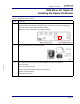
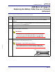
11 Disconnect the ribbon cable from the communication board.
12 Remove the two screws fastening the module to the back panel. Retain the screws for later use.
Remove the digital I/O module and ribbon cable.
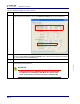
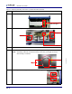
13 To install a digital I/O module, use a flat-head screwdriver to pry the cover plate off the
instrument’s back panel.
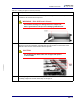
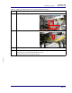
14 Slide the new Digital I/O Module through the hole in the back panel so that the two threaded
studs protrude through. Use the retained screws to secure it in place.
Table 22-1 Installing the digital I/O module (continued)
Step Description