
Operating Manual Instruction Manual

5 - 24
PN 074-519-P1C
3000 Micro GC Operating Manual
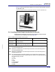
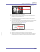
5.1.6.3.5 Mounting the Heated Sample Conditioners
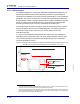
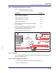
1 Add female nut, front ferrules and back ferrules to the transfer line as shown in
Figure 5-29.
Figure 5-29 Installing female nut, back, and front ferrules onto transfer line
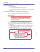
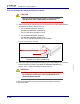
Figure 5-30 Accessory with copper coil and nut installed
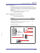
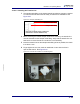
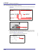
2 Hold the heated sample introduction accessory at an angle to the instrument
and slide the right side screw slots under the loosened 3000 Micro GC cover
screws. See Figure 5-31 and Figure 5-32.
Figure 5-31 Installing the mounting plate onto the 3000 Micro GC
(2-Channel 3000 Micro GC shown, top view)
Female nut
Accessory
sample outlet
Transfer line
Copper coil
1/16 in. back ferrule
3000 Micro GC
sample inlet
1/16 in. front ferrule
Copper coil and
nut installed
3000 Micro GC
Loosen
screws