
Operating Manual Instruction Manual

8 - 19
PN 074-519-P1C
3000 Micro GC Operating Manual
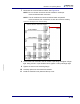
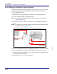
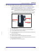
7 Reconnect the communications cables. See Figure 8-23.
NOTE: Do not connect more than two GC modules in series per
communications board connection.
NOTE: The GC modules and communications board use parallel
communications; both connectors on each item function similarly.
Figure 8-23 Examples of GC module cabling
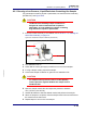
8 Connect the inlet manifold to the GC module input fitting and tighten it finger
tight. Using a 5/16 in. open-ended wrench, tighten 1/4-turn past finger tight.
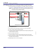
9 Tighten the screw in the mounting flange.
10 Carefully replace the inlet manifold insulation.
11 Install the manifold cover plate and the top cover.
Communication
board
If fan installed
If fan installed
Channel A
Channel B
Channel C
Channel D