
Operating Manual Instruction Manual

5 - 30
PN 074-519-P1C
3000 Micro GC Operating Manual
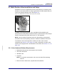
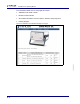
5.2 The Remote Connector
For some applications, an external triggering device may be required for sampling.
This can be accomplished by connecting 3000 Micro GC to the external triggering
device via a Remote Start Cable (PN G2801-60618). This cable has a 15 pin
connector on one end. The other end can be fitted with a desired connector type.
See Table 5-10 and Figure 5-38.
When using EZ IQ control with no external trigger, runs begin and end
automatically depending on Work List status (started, stopped, or paused) and
3000 Micro GC readiness. To have an external triggering device start or cancel a
run, the Digital I/O module (PN G2847A) must be installed in 3000 Micro GC. If the
Digital I/O module is not already installed, see Installing the Digital IO Module Quick
Start Guide.
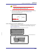
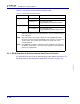
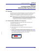
Figure 5-38 Remote start/cancel connector pin outputs
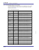
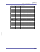
Table 5-10 Remote start/cancel connector pin outputs
Pin Function Wire Color
1 Provides 5 mA for remote input Black
2 REMOTE_START input White
3 REMOTE_START input Red
4 Variable GND Green
5 Provides "5 V pull up" for logic output Orange
6 Provides "5 V pull up" for logic output Blue
7 Contact closure output FAULT_OUT* White/black
8 Contact closure output READY_OUT Red/black
9 Provides 5 mA for remote input Green/black
10 REMOTE_CANCEL input Orange/black
11 REMOTE_CANCEL input Blue/black
12 Variable GND Black/white
13 GND Red/white
14 Contact closure output FAULT_OUT* Green/white
15 Contact closure output READY_OUT Blue/white
*Not implemented