Cover Page O P E R A T I N G M A N U 3000 Micro GC Gas Analyzer PN 074-519-P1C A L
Title Page O P E R A T I N G M A N U 3000 Micro GC Gas Analyzer PN 074-519-P1C www.inficon.com ©2013 INFICON re achus@inficon.
Trademarks The trademarks of the products mentioned in this manual are held by the companies that produce them. 3000 Micro GC™, Bring the Lab to the Sample™, EZ IQ™ and INFICON® are trademarks of INFICON GmbH Genie® (filter) is a registered trademark of A+ Corporation, LLC Luer-Lok® is a registered trademarks of Becton Dickinson. Stabilwax® is a registered trademark of Restek Corporation. Swagelok® is a registered trademark of Swagelok Co. Teflon® is a registered trademarks of E. I.
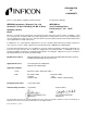
DECLARATION OF CONFORMITY This is to certify that this equipment manufactured by: Design Control Authority INFICON Instruments ( Shanghai ) Co., Ltd INFICON Inc. Two Technology Place East Syracuse, NY 13057 USA Section B, 1/F, No.11 Building, 201 Min Yi Road Shanghai, 201612, China Meets the essential safety requirements of the European Union and is placed on the market accordingly.
Warranty WARRANTY AND LIABILITY - LIMITATION: Seller warrants the products manufactured by it, or by an affiliated company and sold by it, and described on the reverse hereof, to be, for the period of warranty coverage specified below, free from defects of materials or workmanship under normal proper use and service.
3000 Micro GC Operating Manual Table Of Contents Trademarks Disclaimer Copyright Declaration Of Conformity Warranty Chapter 1 Introduction 1.1 1.2 1.3 1.3.1 1.4 1.5 About the Instrument . . . . . . . . . . . . . . . . . . . . . . . . . . . . . . . . . . . . . . . . . . 1-1 Definition of Notes, Warnings and Cautions. . . . . . . . . . . . . . . . . . . . . . . . . 1-3 Safety Overview . . . . . . . . . . . . . . . . . . . . . . . . . . . . . . . . . . . . . . . . . . . . . . 1-4 Cleaning 3000 Micro GC . .
3.2.2 3.2.3 3.3 3.3.1 3.3.2 3.3.3 3.3.3.1 3,4-Channel Chassis . . . . . . . . . . . . . . . . . . . . . . . . . . . . . . . . . . . . . . . . . . 3-3 Portable Chassis . . . . . . . . . . . . . . . . . . . . . . . . . . . . . . . . . . . . . . . . . . . . . 3-4 The 3000 Micro GC Module . . . . . . . . . . . . . . . . . . . . . . . . . . . . . . . . . . . . . 3-5 Principle of 3000 Micro GC Module Operation. . . . . . . . . . . . . . . . . . . . . . . 3-5 Injector Flow Assembly . . . . . . . . . . . . . . . .
PN 074-519-P1C 3000 Micro GC Operating Manual 4.1.3 4.1.3.1 Site Requirements . . . . . . . . . . . . . . . . . . . . . . . . . . . . . . . . . . . . . . . . . . . . 4-2 Electrical Requirements . . . . . . . . . . . . . . . . . . . . . . . . . . . . . . . . . . . . . . . . 4-2 4.1.3.2 Space and Venting Requirements . . . . . . . . . . . . . . . . . . . . . . . . . . . . . . . . 4-2 4.1.4 4.1.5 4.1.5.1 computer Requirements . . . . . . . . . . . . . . . . . . . . . . . . . . . . . . . . . . . . . . .
3000 Micro GC Operating Manual Chapter 5 5.1 5.1.1 5.1.2 5.1.3 5.1.3.1 Sample Conditioners . . . . . . . . . . . . . . . . . . . . . . . . . . . . . . . . . . . . . . . . . . 5-1 List of Sample Conditioners and IPNs . . . . . . . . . . . . . . . . . . . . . . . . . . . . . 5-1 Installing the 10 Micron Sample Inlet Filter . . . . . . . . . . . . . . . . . . . . . . . . . 5-3 Installing the Genie Filter Assembly . . . . . . . . . . . . . . . . . . . . . . . . . . . . . . . 5-3 Tools Required . . . . . . . .
3000 Micro GC Operating Manual Chapter 6 Instrument Setup Through Embedded Web Page Operation 6.1 6.1.1 6.1.2 6.2 6.2.1 6.2.2 6.3 6.3.1 6.3.2 6.3.3 6.3.4 6.3.5 6.3.6 6.4 6.5 6.5.1 6.5.2 Overview. . . . . . . . . . . . . . . . . . . . . . . . . . . . . . . . . . . . . . . . . . . . . . . . . . . . 6-1 Determine Basic 3000 Micro GC Configuration . . . . . . . . . . . . . . . . . . . . . . 6-1 Determining 3000 Micro GC Advanced Configuration . . . . . . . . . . . . . . . . . 6-3 Status . . . . . . . . . . .
7.10.2 7.10.2.1 Common Integration Events. . . . . . . . . . . . . . . . . . . . . . . . . . . . . . . . . . . . 7-22 Width . . . . . . . . . . . . . . . . . . . . . . . . . . . . . . . . . . . . . . . . . . . . . . . . . . . . . 7-22 7.10.2.2 Threshold . . . . . . . . . . . . . . . . . . . . . . . . . . . . . . . . . . . . . . . . . . . . . . . . . . 7-22 7.10.2.3 Integration Off. . . . . . . . . . . . . . . . . . . . . . . . . . . . . . . . . . . . . . . . . . . . . . . 7-23 7.10.3 7.10.3.
3000 Micro GC Operating Manual Chapter 8 PN 074-519-P1C Instrument Operations 8.1 8.1.1 8.1.2 8.1.3 8.2 8.2.1 8.2.2 8.2.3 8.2.4 8.2.5 8.2.6 8.2.7 8.2.8 8.3 8.3.1 8.3.1.1 Routine Operation . . . . . . . . . . . . . . . . . . . . . . . . . . . . . . . . . . . . . . . . . . . . 8-1 System Bakeout . . . . . . . . . . . . . . . . . . . . . . . . . . . . . . . . . . . . . . . . . . . . . . 8-1 Shutdown/Restart . . . . . . . . . . . . . . . . . . . . . . . . . . . . . . . . . . . . . . . . . . . . .
3000 Micro GC Operating Manual 8.5.2 8.5.2.1 Battery Usage Information . . . . . . . . . . . . . . . . . . . . . . . . . . . . . . . . . . . . . 8-38 To View the Battery Status. . . . . . . . . . . . . . . . . . . . . . . . . . . . . . . . . . . . . 8-39 8.5.2.2 Charging the Battery . . . . . . . . . . . . . . . . . . . . . . . . . . . . . . . . . . . . . . . . . 8-39 8.5.2.3 Replace the Battery . . . . . . . . . . . . . . . . . . . . . . . . . . . . . . . . . . . . . . . . . . 8-40 8.5.3 8.5.3.
3000 Micro GC Operating Manual Chapter 10 Service and Technical Support 10.1 10.2 10.3 10.4 How to Contact Customer Support. . . . . . . . . . . . . . . . . . . . . . . . . . . . . . . 10-1 Returning 3000 Micro GC to INFICON . . . . . . . . . . . . . . . . . . . . . . . . . . . . 10-1 Warranty Extension . . . . . . . . . . . . . . . . . . . . . . . . . . . . . . . . . . . . . . . . . . 10-1 Service Contract . . . . . . . . . . . . . . . . . . . . . . . . . . . . . . . . . . . . . . . . . . . . .
3000 Micro GC Operating Manual PN 074-519-P1C This page is intentionally blank.
3000 Micro GC Operating Manual Chapter 1 Introduction This operating manual describes the use and maintenance of the INFICON 3000 Micro Gas Chromatograph (GC). 3000 Micro GC can be used to analyze alternative fuels such as natural gas, syngas, biogas, and landfill gas. Additional applications include: refinery gases, mine gas, furnace gas, custody transfer, well logging, environmental screening, storage tank analysis, scrubber analyses, and monitoring volatile organic compounds (VOC).
3000 Micro GC Operating Manual Table 1-1 Summary of connections Connection Notes Input fitting(s) 1/16 in.
3000 Micro GC Operating Manual 1.2 Definition of Notes, Warnings and Cautions When using this manual, please pay attention to the Notes, Cautions, and Warnings found throughout. For the purposes of this manual they are defined as follows: NOTE: Pertinent information that is useful in achieving maximum 3000 Micro GC efficiency when followed. CAUTION Failure to heed these messages could result in damage to 3000 Micro GC. WARNING Failure to heed these messages could result in personal injury.
3000 Micro GC Operating Manual 1.3 Safety Overview 3000 MicroGC meets IEC (International Electro-technical Commission) classifications: Safety Class III, Transient Overvoltage Category II, Pollution Degree 2. WARNING 3000 Micro GC has been designed and tested in accordance with recognized safety standards and is designed for indoor use. WARNING If 3000 Micro GC is used in a manner not specified by the manufacturer, the protection provided by 3000 Micro GC may be impaired.
3000 Micro GC Operating Manual WARNING 3000 Micro GC has inlets which can be heated to 140°C. Touching the inlets once they are at operating temperatures can result in injury. Extreme care should be taken to avoid touching the inlets. WARNING Do not operate in an explosive environment or in the presence of flammable gases or fumes. Operation of any electrical instrument in such environments constitutes a safety hazard. WARNING Use only the INFICON supplied power source.
3000 Micro GC Operating Manual CAUTION - Static Sensitive Device Electrostatic discharge (ESD) is a threat to electronics. Electrostatic discharge can damage the circuit boards in the instrument. Do not handle the circuit boards. WARNING Hydrogen (H2) gas is flammable and can present an explosion hazard. Leaks, when confined in an enclosed space, may create an ignition or explosion hazard. In any application using hydrogen, leak test all plumbing connections before operating 3000 Micro GC.
3000 Micro GC Operating Manual 1.4 Electromagnetic Compatibility 3000 Micro GC complies with the requirements of CISPR 11 and EN 61326.
3000 Micro GC Operating Manual PN 074-519-P1C This page is intentionally blank.
3000 Micro GC Operating Manual Chapter 2 Specifications 2.1 3000 Micro GC Specifications Table 2-1 Specifications 3 or 4-channel 3000 Micro GC Portable 3000 Micro GC Main voltage 100-240 V (ac) 100-240 V (ac) 100-240 V (ac) 115/230 V (ac) 115/230 V (ac) Power 100 VA 130 VA 130 VA 1.2/0.6 A 1.2/0.6 A 50-60 Hz 50-60 Hz 50-60 Hz 50-60 Hz 50-60 Hz 15 cm 15.5 cm 15.5 cm 15 cm 15 cm (6 in.) (6.1 in.) (6.1 in.) (6 in.) (6 in.) 25 cm 48 cm 36.4 cm 12.5 cm 12.5 cm (10 in.) (18.
3000 Micro GC Operating Manual 2.2 Environmental Conditions The following specifications are applicable to the 3000 Micro GC Heated Regulator and Heated Vaporizer sample conditioners. Operating temperature range. . . . . . 0 to 50°C Relative humidity . . . . . . . . . . . . . . . 5 to 95% (non-condensing) Altitude . . . . . . . . . . . . . . . . . . . . . . . 4572 m (15000 ft.) Usage location . . . . . . . . . . . . . . . . . Temperature controlled environment 2.3 Instrument Specifications 2.3.
3000 Micro GC Operating Manual 2.3.5 Repeatability Typical results for Relative Standard Deviation (RSD) at constant temperature and pressure (for C1 to C6 components at % level) are shown below for peak areas. Injector Type Peak Area Repeatability Variable volume . . . . . . . . . . . . . . . . <1% RSD Fixed volume . . . . . . . . . . . . . . . . . . <0.2% RSD Backflush (timed mode) . . . . . . . . . . <1% RSD Backflush (fixed mode) . . . . . . . . . . . <0.5% RSD 2.3.
00 Micro GC Operating Manual 2.3.10 Safety and Regulatory Standards Conforms to the following safety standards: CSA/National Recognized Test Laboratory (NRTL) UL61010-1 International Electrotechnical Commission (IEC) 61010-1 Canadian Standards Association (CSA) C22.2 No.
3000 Micro GC Operating Manual Chapter 3 Overview 3.1 Overview of 3000 Micro GC Instrument and Accessories 3000 Micro GC is a gas analyzer with applications ranging from fixed gases (H2, O2, N2, CO, CO2, etc.) to light hydrocarbons (methane, ethane, ethylene, propane, butanes, and pentanes) and volatile organic compounds (methanol, ethanol, benzene, etc.). 3000 Micro GC contains from 1 to 4 channels that perform analysis in seconds.
3000 Micro GC Operating Manual 3.2 3000 Micro GC Chassis There are three types of 3000 Micro GC chassis that house GC modules: 1,2-Channel Chassis, see section 3.2.1 on page 3-2 3,4-Channel Chassis, see section 3.2.2 on page 3-3 Portable Chassis, see section 3.2.3 on page 3-4 3.2.1 1,2-Channel Chassis The 1,2-channel chassis can accept one or two channels. The carrier gas and power for a 1,2-channel system must be supplied externally. See Figure 3-1 and Figure 3-2.
3000 Micro GC Operating Manual 3.2.2 3,4-Channel Chassis The 3,4-channel chassis can accept three or four channels. The carrier gas and power for a 3,4-channel system must be supplied externally. See Figure 3-3 and Figure 3-4.
3000 Micro GC Operating Manual 3.2.3 Portable Chassis Portable 3000 Micro GC is a completely self-contained, miniaturized gas chromatograph specifically designed for fast, accurate analysis in the field. Each instrument contains one or two GC channels and an internal carrier gas cylinder. Rechargeable battery packs and automobile power cable options are available for alternative power sourcing. See Figure 3-5, Figure 3-6, and Figure 3-7.
3000 Micro GC Operating Manual 3.3 The 3000 Micro GC Module 3000 Micro GC utilizes a modular GC platform, which can simultaneously analyze samples from one to four independent 3000 Micro GC channels. Each channel (or module) is a self-contained GC that performs sample injection, separation, and detection on a set of target components. When installed in a 3000 Micro GC chassis, a module is referred to as a channel. When standalone, it is referred to as a module.
3000 Micro GC Operating Manual 2 Separation: As the sample gas enters the column, its component gases are separated based on their retention or adsorption property with the column stationary phase material. The longer the component gas is retained by the column, the later it will elute from of the column for detection. Components may be separated based on size, polarity, or boiling point, depending on the column.
3000 Micro GC Operating Manual 3.3.
3000 Micro GC Operating Manual 3.3.3 Injectors Depending on application requirements, 3000 Micro GC supports four different types of injectors. These MEMS based injector “wafers” contain sample loops etched into the wafer and micro-diaphragm valves used to direct sample and carrier gas flow. The sample volume is controlled in EZ IQ by the Inject Time in milliseconds (ms). The Injector Temperature can be set from 40-100°C or be turned off. 3.3.3.
3000 Micro GC Operating Manual 3.3.3.3 Fixed Injector Fixed Injectors are unique to 3000 Micro GC. Fixed Injectors provide the best accuracy and precision for 0.2% levels and higher. Valid settings are between 0-50 ms. An inject time of 0 ms results in no injection. A typical setpoint is 30 ms. No significant difference in inject volume is achieved from inject times between 15-50 ms. Values less than 15 ms may result in repeatability issues. Actual injection volumes are typically 1-2 µL of gas.
3000 Micro GC Operating Manual 3.3.3.4 Backflush Injector The backflush assembly consists of: a backflush injector a precolumn an analytical capillary column The precolumn is a short section of column, whereas the analytical column is usually longer. The precolumn and analytical column are connected in series. The precolumn functions to prevent contaminants from entering the analytical column. The sample first travels through the precolumn and then through the analytical column.
3000 Micro GC Operating Manual 3.3.4 Columns 3000 Micro GC utilizes capillary columns for separation. Two types of capillary columns are used: Porous Layer Open Tubular (PLOT) and Wall Coated Open Tubular (WCOT). The capillary columns are wound into a column can, which is installed into a module and can be heated up to 180°C. Columns are connected to the injector on one end and the TCD on the other end using small dead-volume fittings. Typical column flow rates range from 0.
3000 Micro GC Operating Manual 3.3.5 Detector 3000 Micro GC uses a MEMS based TCD, which has a 240 nL internal cell volume. (See Figure 3-12.) The small volume provides for excellent sensitivity. For some components, a detection limit of 1 ppm can be achieved. NOTE: TCD sensitivity is matrix, carrier gas, and component dependent. The TCD uses a Wheatstone bridge design and has a sample and reference channel.
3000 Micro GC Operating Manual 3.3.7 Module Cases 3000 Micro GC supports two types of module cases, a standard module case and a Modbox module case. 3.3.7.1 Standard Module Case The standard module case is used for most column types. MolSieve modules are an exception. See Figure 3-13. Figure 3-13 Standard module 3.3.7.2 Modbox Module Case The Modbox module allows the column to be wound in a larger diameter.
3000 Micro GC Operating Manual 3.4 3000 Micro GC Chassis Components 3000 Micro GC modules are installed into the 3000 Micro GC chassis. The components that are integrated into the chassis are: Inlet Tubing, see section 3.4.1 on page 3-14 C-Board, see section 3.4.2 on page 3-15 OBC Board, see section 3.4.3 on page 3-15 Sample Pump, see section 3.4.4 on page 3-16 Carrier Gas Weldment, see section 3.4.5 on page 3-17 Carrier Gas Inlet, see section 3.4.
3000 Micro GC Operating Manual 3.4.2 C-Board The Communications Board, also known as the C-board is internally mounted on the side of 3000 Micro GC. It controls the inlet zone heater and communicates with the D-boards and onboard computer. 3.4.3 OBC Board The onboard computer (OBC) is internally mounted on the back of 3000 Micro GC. It is the main processor which communicates with the C-board and the external control system.
3000 Micro GC Operating Manual 3.4.4 Sample Pump One or two sample pumps are installed internally in 3000 Micro GC. There is no flow through the sample path until the pump turns on. When the sample pump turns on, the sample is drawn through the sample inlet tubing and the sample injectors open for the time specified in the acquisition method. Set pump time at a minimum of 20 seconds. If sufficient sample gas is available, increase the pump time to 60 seconds. The sample pump draws at a rate of 10 mL/min.
3000 Micro GC Operating Manual 3.4.5 Carrier Gas Weldment The carrier gas weldment connects the carrier gas to each module. It consists of a base plate and stainless steel tubing. Base plates align to each module. NOTE: See section 8.2, Remove and Replace a 3000 Micro GC Module, on page 8-5 for more information about how to align a module.
3000 Micro GC Operating Manual 3.4.6 Carrier Gas Inlet One or two carrier gases can be configured with the carrier gas inlets located on the rear of 3000 Micro GC. See Figure 3-20, Figure 3-21, and Figure 3-22.
3000 Micro GC Operating Manual 3.4.7 Vents Analytical vents expel sample gas and carrier gas mixture from the sample side of the TCD. Reference vents expel carrier gas from the reference side of the TCD. Sample vents expel sample gas when the sample pump is drawing sample gas into sample loop or the sample is backflushed from pre-column out of 3000 Micro GC. See Figure 3-23, Figure 3-24 and Figure 3-25.
3000 Micro GC Operating Manual 3.4.8 Remote Control Module The Remote Control Module allows an external control system to start 3000 Micro GC. The Remote Control Module port is located on the rear of 3000 Micro GC. See Figure 3-26. PN 074-519-P1C Figure 3-26 Remote connector on the rear panel.
3000 Micro GC Operating Manual 3.5 Sample Conditioners CAUTION 3000 Micro GC is a gas-only analyzer! Extreme caution must be taken to ensure that liquid and solid particles are not introduced into 3000 Micro GC. A 10 micron sample inlet filter (PN G2801-60900) is provided in the 3000 Micro GC ship kit and must be connected to instrument sample inlet at installation.
3000 Micro GC Operating Manual 3.6 EZ IQ Chromatography Software EZ IQ is a powerful chromatography software running under the Microsoft Windows® operating system with an easy-to-use graphical user interface. EZ IQ supports three languages: English, Chinese, and Japanese. See Figure 3-27.
3000 Micro GC Operating Manual 3.7 Product Identification Each 3000 Micro GC carries a configuration specific part number (PN:), serial number (SN:) and identification number (ID:). When contacting INFICON regarding a 3000 Micro GC, please have all three product identification numbers available. See Figure 3-28. PN 074-519-P1C Figure 3-28 3000 Micro GC product label.
3000 Micro GC Operating Manual 3.7.1 1,2-Channel and Portable 3000 Micro GC Part Numbering The 1,2-channel 3000 Micro GC chassis and the Portable 3000 Micro GC chassis can be equipped with one or two channels (modules). Figure 3-29 shows how an instrument part number is constructed for both types of chassis.
3000 Micro GC Operating Manual 3.7.2 3,4-Channel 3000 Micro GC Part Numbering The 3,4-channel 3000 Micro GC chassis can be equipped with three or four channels (modules). Figure 3-30 shows how an instrument part number is constructed for a 3,4-channel chassis.
3000 Micro GC Operating Manual 3.7.4 Identification Number Each instrument is uniquely identified by an identification number (ID:). See Figure 3-31.
3000 Micro GC Operating Manual Chapter 4 Installation 4.1 Site Preparation Before installation, make sure that the installation site is fully prepared. Contact INFICON with any question regarding site preparation. 4.1.1 List of Required Tools Adjustable wrench (small) Adjustable wrench (large) Two 7/16 in. open-ended wrenches 9/16 in. open-ended wrench 5/16 in. open-ended wrench 1/4 in. open-ended wrench Tubing cutter Teflon® tape 4.1.
3000 Micro GC Operating Manual 4.1.3 Site Requirements 4.1.3.1 Electrical Requirements A standard 100 to 240 V(ac) electrical outlet is required. A Universal/Uninterruptable Power Supply (UPS) or surge protector is recommended. 4.1.3.2 Space and Venting Requirements For optimum 3000 Micro GC performance and lifetime, allow unrestricted airflow around 3000 Micro GC to dissipate heat.
3000 Micro GC Operating Manual 4.1.5 Gas and Regulator Requirements 4.1.5.1 Carrier Gas and Regulator Requirements A continuous, controlled flow of carrier gas is required. Use high purity grade gas specifically intended for chromatographic use. All carrier gas types should be 99.995% to 99.9995% pure. The carrier gas tank requires a dual stage regulator capable of delivering 80 to 82 PSI of gas pressure. The regulator outlet fitting must be adapted to Swagelok in order to connect the tubing. Use 1/8 in.
3000 Micro GC Operating Manual 4.2 Instrument Hardware Setup 4.2.1 Unpacking the Instrument Verify the contents of the order, including software, sample conditioners, and checkout gases, against the packing list. The contents of the shipping kit should also be verified. 4.2.2 Shipping Kit Contents A PN 074-542-P1 3000 Micro GC Shipping Kit Packing List is included with each instrument package. This packing list will indicate which items are included for a particular instrument configuration. 4.2.2.
3000 Micro GC Operating Manual 4.2.2.2 Configuration Dependent Parts 4.2.2.2.1 1,2-Channel and 3,4-Channel 3000 Micro GC Specific Parts PN Description Quantity G2801-60747 . . . 24 V (dc) AC/DC Power Supply . . . . . . . . . . . 1 pc 4.2.2.2.2 Portable 3000 Micro GC Specific Parts PN Description Quantity PNU-2058. . . . . . Onboard Carrier Gas Refiller Apparatus . . . . . 1 pc G2801-60748 . . . 15 V (dc) AC/DC Power Supply . . . . . . . . . . . 1 pc 4.2.2.2.
3000 Micro GC Operating Manual 4.2.3 Making Carrier Gas and Sample Inlet Connectors 3000 Micro GC is equipped with a 1/8 in. carrier gas Swagelok connector on the back of the instrument. This section demonstrates how to assemble 1/8 in. carrier gas tubing with the instrument. The following procedure reviews how to make Swagelok connections. This procedure explains how to connect tubing to a fitting, such as the sample inlet(s), carrier gas inlet(s), or the gas supply tank. Materials Needed 1/8 in.
3000 Micro GC Operating Manual 4 Ensure that the front ferrule makes contact with the female fitting, slide the Swagelok nut over the ferrule, then finger tighten. See Figure 4-2. Figure 4-2 Vise fitting assembly Female fitting in vise Front ferrule, back ferrule, and nut 5 Push the tube fully into the female fitting. 6 Mark the Swagelok fitting with a pencil line as shown in Figure 4-3. Figure 4-3 Pencil line Pencil line 7 Tighten the 1/8 in.
3000 Micro GC Operating Manual 4.2.4 Connecting the Carrier Gas 4.2.4.1 Gas Safety WARNING Gas cylinders present a hazard when not secured properly. Securely fasten all compressed gas cylinders to an immovable structure or permanent wall. Store and handle compressed gases in accordance with safety procedures. WARNING Gas cylinders may present a hazard under extreme temperature conditions. Do not store gas cylinders in the path of heated oven exhausts or other sources of heat.
3000 Micro GC Operating Manual 4.2.4.2 Connecting the Carrier Gas Particulate Filter 1 Remove any shipping caps on 3000 Micro GC. 2 Install one carrier gas particulate filter (PN 3150-0602) on the carrier gas supply tubing for each carrier gas used (see Figure 4-5). Do not connect the tubing to 3000 Micro GC at this time. Figure 4-5 Carrier gas particulate filter setup Particulate Filter (3150-0602) Arrow points to 3000 Micro GC Cutoff valve (not provided) 15 cm (6 in.
3000 Micro GC Operating Manual 4.2.4.3 Setting the Gas Pressure Set the carrier gas regulator as shown in Table 4-1. Table 4-1 Carrier gas input pressure Carrier Gas Required Delivery Pressure helium* 552 +/- 14 kPa (80 +/- 2 PSI) hydrogen* 552 +/- 14 kPa (80 +/- 2 PSI) argon 552 +/- 14 kPa (80 +/- 2 PSI) nitrogen 552 +/- 14 kPa (80 +/- 2 PSI) * Required for checkout WARNING Never fill the Portable 3000 Micro GC internal gas cylinder with hydrogen.
3000 Micro GC Operating Manual 4.2.4.5 Connecting the Carrier Gas to the 3000 Micro GC 1 Connect the carrier gases to the instrument via the 1/8 in. Swagelok fitting(s) located on the back of the instrument. See section 4.2.3 on page 4-6. WARNING If a hazardous sample is used, the sample exhaust must be vented to a fume hood or other designated area for hazardous waste disposal. CAUTION Do not use leak detection fluids. 4.2.4.
3000 Micro GC Operating Manual Figure 4-7 Portable 3000 Micro GC, back view Analytical column vents Reference column vents Sample pump vents CARRIER OUT port for onboard cylinder Carrier jumper tube CARRIER IN ports 4 Set the carrier switch on the front of Portable 3000 Micro GC to ON. 5 Connect sample gases. WARNING 4.2.
3000 Micro GC Operating Manual 4.2.5.2 Tools Required Two 7/16 in. wrenches, for the sample inlet filter assembly One 5/16 in. wrench, for user sample line to sample inlet filter 4.2.5.3 Sample Inlet Filter Assembly Installation 1 Shut off any sample flow to 3000 Micro GC. 2 Allow the sample inlet to cool. 3 Disconnect the sample line to the 3000 Micro GC input fitting using the 5/16 in. wrench, while holding the sample inlet filter with a 7/16 in. wrench.
3000 Micro GC Operating Manual 4.2.6 Power and Communication Cable Setup 1 Connect the crossover cable (PN 5183-4649) between the computer and 3000 Micro GC. NOTE: If a LAN connection through a hub is required, consult an IT specialist to configure the setup. 2 Connect the power cable to the AC/DC converter supplied in the Shipping Kit. 3 If desired, connect the remote start cable (PN G2801-60618) to 3000 Micro GC. See section 5.2, The Remote Connector, on page 5-30 for remote start cable pinout details.
3000 Micro GC Operating Manual 4.3 Instrument Configuration Setup 3000 Micro GC can be connected directly to the computer on a LAN using a crossover cable (PN 5183-4649, supplied in the Shipping Kit). Use a crossover cable to establish the initial connection. 4.3.1 Turn on 3000 Micro GC To turn on 3000 Micro GC, set the switch on the front of the instrument to the on position. The switch will illuminate green to indicate that 3000 Micro GC is on.
3000 Micro GC Operating Manual 4.3.2 IP Address Configuration The IP address on the computer must be changed in order to communicate with 3000 Micro GC. Set the IP address as follows, assuming the computer is running Windows XP operation system: 1 Click Start >> Connect To >> Show All Connections. 2 Click Local Area Connection on the Network Connections window. 3 Click the General tab and click Properties. 4 Highlight Internet Protocol (TCP/IP) and click Properties.
3000 Micro GC Operating Manual 4.3.3 Ping the Instrument Ensure that the instrument is turned on and is fully booted up. On the computer, click Start >> Run and type ping 10.1.1.101. Ensure data packets are being received, as shown in Figure 4-12. If data packets are not being received, check the IP settings or consult the troubleshooting table in section 9.1.3, Common Connection Problems, on page 9-8. NOTE: At the factory, the instrument IP address was set to 10.1.1.101.
3000 Micro GC Operating Manual 4.4 Chromatography Software Installation PN 074-519-P1C For an in-depth guide on installing and configuring EZ IQ, refer to the 074-537 EZ IQ Installation Guide.
3000 Micro GC Operating Manual Chapter 5 Accessory Installation 5.1 Sample Conditioners 3000 Micro GC can be damaged by contaminants, especially particulates and condensing aerosols. Use an appropriate filter or sample conditioner at all times. Table 5-1 lists the typical usage and filtration capabilities of the standard filter and available accessories. 5.1.
3000 Micro GC Operating Manual Table 5-1 List of sample conditioners, inlet pressures, and IPNs Type Input Pressure Sample Sample Matrix to Accessory Container/delivery Heated Regulator for Sampling 14 to 5516 kPa (2 to 800 PSI) Heated Vaporizer for 1379 to 5516 kPa LPG Sampling (00 to 800 PSI) Particle filtration (microns) PN Transfer line or high-pressure vessel C6+ components >0.
3000 Micro GC Operating Manual 5.1.2 Installing the 10 Micron Sample Inlet Filter For instruction on installing the 10 micron sample inlet filter (PN G2801-60900), refer to section 4.2.5.3, Sample Inlet Filter Assembly Installation, on page 4-13. 5.1.3 Installing the Genie Filter Assembly The Genie Filter Assembly Kit (PN G2817A) provides gas-liquid separation function through a Genie Membrane Separator. It is not compatible with other sample conditioners mounted on the 3000 Micro GC front panel.
3000 Micro GC Operating Manual 5.1.3.2 User Supplied Parts Fittings for vent tubing, if used Sample input tubing and fittings 5.1.3.3 Installation Instructions for the Genie Filter Assembly 1 Turn off 3000 Micro GC and allow the sample inlet fitting to cool. WARNING 3000 Micro GC has inlets which can be heated to 140°C. Touching the inlets at operating temperatures can result in injury. Extreme care should be taken to avoid touching the heated inlets.
3000 Micro GC Operating Manual 6 Install the sample outlet tube into the output fitting on the Genie Filter Assembly. See Figure 5-3. Tighten 1/2 turn past finger tight using a 1/4 in. open-ended wrench, then loosen 1/4 turn, so that the tube is loose but will not disengage.
3000 Micro GC Operating Manual 8 While maintaining the alignment of the outlet tubing to the inlet fitting, tilt the bracket up and snap it onto the front of the instrument. When properly mounted, the bracket should be flat against the 3000 Micro GC frame. Insert the outlet tubing into the 3000 Micro GC inlet fitting. See Figure 5-5. Figure 5-5 Genie filter assembly, installed Inlet fitting Sample outlet tube installed G2817A on a 2-channel 3000 Micro GC shown 9 Tighten the 1/4 in.
3000 Micro GC Operating Manual 11 Install one end of the sample inlet tubing, 1/4 in. nut, and front and back ferrules provided in the kit onto the sample input fitting on the bottom of the filter as shown in Figure 5-6. Connect the open end of the sample inlet tube to the sample.
3000 Micro GC Operating Manual 5.1.4 Installing the Pressure Reducer The Pressure Reducer (PN G2815A) provides a pressure reducing function. It is not compatible with other sample conditioners mounted on the 3000 Micro GC front panel. Table 5-3 Pressure reducer kit contents. Description Quantity Outlet tube 1 ea Flow controller 1 ea 1/16 in. nut and ferrule set 1 ea Figure 5-8 Pressure reducer kit 1/16 in. female nut and ferrule set Pressure reducer Outlet tube 5.1.4.
3000 Micro GC Operating Manual 5.1.4.3 Installation Instructions for the Pressure Reducer 1 Turn off 3000 Micro GC and allow the sample inlet fitting to cool. WARNING 3000 Micro GC has inlets which can be heated to 140°C. Touching the inlets at operating temperatures can result in injury. Extreme care should be taken to avoid touching the heated inlets. 2 Move the 3000 Micro GC handle fully away from the front cover.
3000 Micro GC Operating Manual 6 Align the Pressure Reducer bracket horizontally on the face of the 3000 Micro GC so that the end of the outlet tubing is near the inlet fitting. Place the lower lip of the mounting bracket under the bottom front panel as shown in Figure 5-11. The edge of the 3000 Micro GC front molding will fit into the groove in the bracket.
3000 Micro GC Operating Manual 10 Install 1/8 in. sample input line to the top right Swagelok fitting on the accessory. See Figure 5-13. Figure 5-13 Installing sample input and vent lines Install sample input line here Install vent line here WARNING If a hazardous sample is used, the sample exhaust must be vented to a fume hood or other designated area for hazardous waste disposal. 11 Connect a vent line to the vent fitting using standard 1/8 in. fittings.
3000 Micro GC Operating Manual 5.1.5 Installing the Pressure Reducer and Genie Filter Assembly The Pressure Reducer and Genie Filter Assembly (G2816A) provides a pressure reducing function and a gas-liquid separation through a Genie filter. It is not compatible with other sample conditioners mounted on the 3000 Micro GC front panel. See Table 5-4 and Figure 5-15 for G2816A kit content. Table 5-4 Pressure reducer and Genie filter assembly kit contents.
3000 Micro GC Operating Manual 5.1.5.3 Installation Instructions for the Pressure Reducer and Genie Filter Assembly 1 Turn off 3000 Micro GC and wait for the sample inlet fitting to cool. WARNING 3000 Micro GC has inlets which can be heated to 140°C. Touching the inlets at operating temperatures can result in injury. Extreme care should be taken to avoid touching the heated inlets. 2 Move the 3000 Micro GC handle fully away from the front cover.
3000 Micro GC Operating Manual 6 Insert the outlet tube into the outlet fitting on the Genie Filter Assembly. See Figure 5-17. Tighten 1/2 turn past finger tight using the 1/4 in. open-ended wrench, then loosen 1/4 turn so that the tube is loose but will not disengage.
3000 Micro GC Operating Manual 8 When maintaining the alignment of the outlet tubing and the inlet fitting, tilt the bracket up and snap it onto the front of the 3000 Micro GC. When properly mounted, the bracket should be flat against the 3000 Micro GC frame. Insert the outlet tubing into the sample inlet fitting. See Figure 5-19.
3000 Micro GC Operating Manual 12 Remove the blue cap from the 1/8 in. NPT male input fitting and install a user-provided 1/8 in. female NPT fitting and sample line. See Figure 5-20. Figure 5-20 Installing the sample line Tighten Tighten Flow adjustment knob Remove blue cap from NPT fitting and install sample line PN G2816A WARNING If a hazardous sample is used, the sample exhaust must be vented to a fume hood or other designated area for hazardous waste disposal.
3000 Micro GC Operating Manual Figure 5-22 shows the Pressure Reducer and Genie Filter Assembly mounted on 3000 Micro GC. Figure 5-22 Pressure reducer and Genie filter assembly mounted on 3000 Micro GC G2816A on a 2-channel 3000 Micro GC 5.1.6 Installing Heated Sample Introduction Accessories Heated sample introduction accessories are separately powered sample conditioners for the 3000 Micro GC. See Table 5-5.
3000 Micro GC Operating Manual 5.1.6.1 Heated Regulator The Heated Regulator for natural gas (PN G2818A-X/G2845A-X/G2857A-X) is a separately powered accessory that reduces the pressure of a gas sample for introduction into 3000 Micro GC while maintaining the sample in a non-condensed gas phase. This device is designed for use with natural gas samples introduced through sample vessels or through sample lines connected to wellheads or transfer points.
3000 Micro GC Operating Manual 5.1.6.1.1 Target Analytes Natural gas typically consists of methane and a wide distribution of other hydrocarbons and fixed gases. The Heated Regulator is designed for the broadest range of sample compositions that are in the gas phase at ambient temperature and pressure. NOTE: The Heated Regulator is not intended for use with natural gas liquid (NGL) samples. 5.1.6.1.
3000 Micro GC Operating Manual 5.1.6.2 Heated Vaporizer The Heated Vaporizer (PN G2819A-X/G2846A-X/G2858A-X) is used for high pressure liquefied petroleum gas (LPG). This sample enters a pressure regulator in the vaporizer where it expands, reducing the pressure to 52 ±17 kPa (7.5 ±2.5 PSI). The sample is introduced into the injector through the transfer line at a flow rate of approximately 40 mL/min. To prevent sample condensation, the vaporizer temperature is regulated at 100 ±5°C.
3000 Micro GC Operating Manual 5.1.6.2.1 Heated Vaporizer Accessory Contents Table 5-8 Heated vaporizer accessory contents (PN G2819A-X/G2846A-X/G2858A-X) Description Quantity Heated Vaporizer assembly, with copper coil extension installed 1 ea Copper high pressure vent tubing 1 ea Tygon low pressure vent tubing 1 ea Power supply and cable 1 ea Filter disconnect assembly (includes inline filter and disconnect fitting) 1 ea Transfer line kit (two each transfer lines, insulation, 1/16 in.
3000 Micro GC Operating Manual 5.1.6.3.2 User Supplied Parts T20 Torx screwdriver 1/16 in. stainless steel tubing for low pressure venting 1/8 in. copper tubing for high pressure venting (rated for the maximum supply pressure) 5.1.6.3.3 Prepare the 3000 Micro GC and Sample Introduction Accessory 1 Turn off 3000 Micro GC and allow the sample inlet fitting to cool. WARNING 3000 Micro GC has inlets which can be heated to 140°C. Touching the inlets at operating temperatures can result in injury.
3000 Micro GC Operating Manual 5.1.6.3.4 Installing the Transfer Line 1 The sample outlet fitting on the heated sample introduction accessory contains a nut and ferrule set and should be ready for transfer line installation. See Figure 5-27.
3000 Micro GC Operating Manual 5.1.6.3.5 Mounting the Heated Sample Conditioners 1 Add female nut, front ferrules and back ferrules to the transfer line as shown in Figure 5-29. Figure 5-29 Installing female nut, back, and front ferrules onto transfer line Female nut 1/16 in. back ferrule Accessory sample outlet 3000 Micro GC sample inlet 1/16 in.
3000 Micro GC Operating Manual Figure 5-32 Installing the heated sample instroduction accessory on 3000 Micro GC Sample inlet fitting Transfer line 3 Tighten the 3000 Micro GC cover screws. 4 Insert the transfer line into the 3000 Micro GC sample inlet fitting as far as possible, then back it out about 1 mm. 5 Finger tighten the female nut, then tighten an additional 1/8 turn with the 5/16 in. open-ended wrench.
3000 Micro GC Operating Manual 5.1.6.3.6 Install the Vent Tubing and Connect to Power CAUTION Never connect low and high pressure vent lines together. 3000 Micro GC will be damaged by back pressure. 1 Attach low pressure vent tubing to the low pressure vent on the heated sample introduction accessory. See Figure 5-34.
3000 Micro GC Operating Manual WARNING Keep the power supply block away from gas inlets or other areas where gas may collect or leak. 3 Fasten the power supply cable to the heated sample introduction accessory. Connect the power supply to a power source. See Figure 5-35. Figure 5-35 Connecting the power cord G2819A-X Attach power supply cable 4 Turn 3000 Micro GC on. 5.1.6.
3000 Micro GC Operating Manual 5.1.6.5 Heated Regulator/Vaporizer Part Numbers The Heated Regulator and Heated Vaporizer are supplied with country specific power cords. Part numbers reflect the power cord provided with the sample conditioner. See Table 5-9.
3000 Micro GC Operating Manual Table 5-9 Heated regulator/vaporizer IPNs (continued) Power Cord Description G2846A-6 Australia/NZ Heated Vaporizer for gas sampling:3,4-ch G2846A-7 Korea Heated Vaporizer for gas sampling:3,4-ch G2857A-1 China Heated Regulator for gas sampling: portable G2857A-2 Europe Heated Regulator for gas sampling: portable G2857A-3 US Heated Regulator for gas sampling: portable G2857A-4 Japan Heated Regulator for gas sampling: portable G2857A-5 UK/HK/SG/MY Heated
3000 Micro GC Operating Manual 5.2 The Remote Connector For some applications, an external triggering device may be required for sampling. This can be accomplished by connecting 3000 Micro GC to the external triggering device via a Remote Start Cable (PN G2801-60618). This cable has a 15 pin connector on one end. The other end can be fitted with a desired connector type. See Table 5-10 and Figure 5-38.
3000 Micro GC Operating Manual Figure 5-39 shows the remote start cable. Figure 5-39 G2801-60618 remote start cable Figure 5-40 shows the remote start/cancel circuitry.
3000 Micro GC Operating Manual Table 5-11 shows the remote start/cancel action matrix.
3000 Micro GC Operating Manual 5.3 Multi-Position Valve Installation and Setup 3000 Micro GC can be equipped with a Valco (VICI) switching or sampling valve actuator to control the injection of multiple gas streams. EZ IQ software allows for control of this stream selection valve. See Figure 5-41.
3000 Micro GC Operating Manual 5.3.2 Valve Hardware Connections 1 Assemble the multiposition microelectric valve actuator and controller connections according to the Valco operating manual. 2 Connect the Serial Port Cable (RS-232) to computer for valve control. 5.3.3 Valve Configuration PN 074-519-P1C The Valco valve driver is built into the EZ IQ software package. For valve configuration steps, see section 7.3, Configuring EZ IQ to Use a Valco (VICI) Valve, on page 7-4.
3000 Micro GC Operating Manual Chapter 6 Instrument Setup Through Embedded Web Page Operation 6.1 Overview 3000 Micro GC has an embedded web page for easy access to features such as viewing configuration information, IP Address modification, and carrier gas modification. The embedded web page is accessed via a web browser. NOTE: 3000 Micro GC is not connected directly to the internet. 3000 Micro GC has an embedded web server.
3000 Micro GC Operating Manual The information listed on the home page will contain: 3000 Micro GC serial number Number of GC modules GC module information such as column, detector, and pump used Carrier gas type PN 074-519-P1C Figure 6-2 3000 Micro GC embedded web page home page 6-2
3000 Micro GC Operating Manual 6.1.2 Determining 3000 Micro GC Advanced Configuration The embedded web page displays detailed configuration information in the Utilities tab. 1 On 3000 Micro GC home page, click the Utilities tab. See Figure 6-3. Figure 6-3 Utilities tab on embedded web page 2 Under Configuration, click Full System. See Figure 6-4.
3000 Micro GC Operating Manual 3 The 3000 Micro GC configuration is displayed. See Table 6-1 and Figure 6-5.
3000 Micro GC Operating Manual Codes for GC modules, sample pumps, and GC module layout are displayed in Figure 6-6.
3000 Micro GC Operating Manual 6.2 Status 6.2.1 Check GC Module Parameters When EZ IQ software is used to download a method, the information is sent to 3000 Micro GC and is displayed in the Status tab. Temperatures and pressures for all GC modules will be listed. See Figure 6-7. NOTE: Temperature and pressure settings cannot be edited in this view. Settings can only be edited within EZ IQ software.
3000 Micro GC Operating Manual 6.2.2 Check the Duty Cycle 1 The duty cycle should be approximately 30 to 40% for column head pressure (CHP) and Delta P (if fixed volume). 2 Is the Duty Cycle between 30 to 40%? 2a YES—Process with analysis. 2b NO—If the duty cycle is > 50%, check the carrier gas inlet pressure. Replace the carrier gas filter (PN 3150-0602). Recheck the Duty cycle. If it is still > 50%, contact INFICON. 6.3 Utilities The Utilities tab is on the 3000 Micro GC embedded web page.
3000 Micro GC Operating Manual 6.3.2 Restart To restart the 3000 Micro GC: 1 On the Utilities tab, click Restart. 2 A countdown screen will count down three minutes. 3 After three minutes have passed, set the front panel power switch to the off position. 4 Set 3000 Micro GC front panel power switch back to the on position. 5 Wait at least three minutes for the 3000 Micro GC to fully reboot. 6.3.3 Shutdown On the Utilities tab, click Shutdown to shut down 3000 Micro GC.
3000 Micro GC Operating Manual 6.4 Change Carrier Gas Configuration The type of carrier gas used for analysis can be changed through the embedded web page. NOTE: If a carrier gas type is changed without following this procedure, inverted peaks will appear in the chromatogram. 1 Open the web browser. 2 In the address bar, type the current IP Address of the instrument. Press Enter. See Figure 6-9. NOTE: At the factory, the instrument IP address was set to 10.1.1.101.
3000 Micro GC Operating Manual 4 Click Make Changes. See Figure 6-10. 5 When prompted for a user name and password, type gasconfig for both. See Figure 6-11. Figure 6-11 Gas type username and password gasconfig gasconfig 6 A window will then appear similar to Figure 6-12. NOTE: Entries m1 and m2 represent Channels A and B respectively. Entries m3 and m4 represent Channels C and D, if installed. 7 Select the carrier gas connection under Connection corresponding to the desired GC module. Click Submit.
3000 Micro GC Operating Manual 8 Select the new carrier gas type from the drop-down list. See Figure 6-13. Figure 6-13 Selecting a new carrier gas type 9 Click Submit. This turns the column heaters off (to cool the columns and avoid thermal shock) and displays the Check Status view. See Figure 6-14. Figure 6-14 Check status view 10 Click Check Status to display a window which shows the current column PN 074-519-P1C temperature(s).
3000 Micro GC Operating Manual 11 Click Continue from the 3000 Micro GC status view to implement the configuration change. 12 Change the gas supply connections at the 3000 Micro GC back panel, and check for leaks. 13 Click Restart. See Figure 6-16. Wait at least three minutes before shutting down the instrument. CAUTION Do not turn off the power without waiting at least three minutes. 3000 Micro GC must update configuration files before power is turned off.
3000 Micro GC Operating Manual 6.5 Change IP Address 6.5.1 IP Configuration The 3000 Micro GC IP address can be changed through the embedded web page. 1 Open the web browser. 2 In the address bar, type the current IP Address of the instrument. Press Enter. See Figure 6-17. NOTE: At the factory, the instrument IP address was set to 10.1.1.101. Figure 6-17 Internet Explorer address bar 3 The instrument embedded web page will display. Click the IP Configuration tab. See Figure 6-18. 4 Click Make Changes.
3000 Micro GC Operating Manual 5 When prompted for a user name and password, type ipconfig for both. See Figure 6-19. Figure 6-19 IP configuration access 6 Type the desired changes to the IP Address and click Submit. See Figure 6-20. NOTE: Consult an IT professional to assist with IP settings.
3000 Micro GC Operating Manual 7 A window will prompt to restart 3000 Micro GC. Click Restart and wait at least three minutes before shutting down the 3000 Micro GC. See Figure 6-21. CAUTION Do not turn off the power without waiting at least three minutes. 3000 Micro GC must update configuration files before power is turned off. If power is turned off too soon, the files could be corrupted, making 3000 Micro GC inoperable. Figure 6-21 IP configuration - restart 8 Turn off 3000 Micro GC.
3000 Micro GC Operating Manual 6.5.2 Access the Embedded Web Page Via a Fixed IP Address If the embedded web page cannot be accessed, and the IP address of the 3000 Micro GC cannot be determined, follow the instructions below to access the web page via a fixed IP address. 1 Connect the 3000 Micro GC to the computer via the crossover cable (PN 5183-4649). 2 Click Start >> Connect To >> Show All Connections. See Figure 6-23. NOTE: This step may differ slightly if a different Windows version is used.
3000 Micro GC Operating Manual 4 On the Local Area Connection Status window, click Properties. See Figure 6-25. Figure 6-25 Local area connection status window 5 On the Local Area Connection Properties window, select Internet Protocol (TCP/IP) from the list, then click Properties. See Figure 6-26.
3000 Micro GC Operating Manual 6 In the Internet Protocol (TCP/IP) Properties window, click Use the following IP address. See Figure 6-27. Figure 6-27 Internet protocol (TCP/IP) properties window 7 Type the IP address and Subnet mask as follows: IP address: 192.168.1.100 Subnet mask: 255.255.255.0 Default gateway*: * Do not type anything here. Gateway and DNS server entries are not used for direct connection. 9 Click OK to exit the Local Area Connection Properties window.
3000 Micro GC Operating Manual 11 Click Start >> Run. 12 Type ping 192.168.1.99. This will open the Command Prompt window. The instrument should populate the window as shown in Figure 6-28. Figure 6-28 Fixed IP address ping 13 Type 192.168.1.99 into the web browser address bar. Press Enter. The instrument embedded web page home page will display. 14 Click IP Configuration. PN 074-519-P1C 15 Review the IP Address. NOTE: If connection cannot be established, verify all LAN connections and IP addresses.
3000 Micro GC Operating Manual PN 074-519-P1C This page is intentionally blank.
3000 Micro GC Operating Manual Chapter 7 Basic EZ IQ Operation 7.1 Introduction EZ IQ is powerful chromatography software running under the Microsoft Windows operating system with an easy to use graphical user interface. EZ IQ supports three languages: English, Chinese, and Japanese. This chapter describes the basic functions of EZ IQ. For more detailed information, refer to the 074-538 EZ IQ Operating Manual.
3000 Micro GC Operating Manual 3 On the Instrument Configuration window, type the desired Instrument Name, select Instrument type: 3000 Micro GC Enhanced Driver, and click Configure. See Figure 7-2. Figure 7-2 Instrument configuration window 4 The 3000 Micro GC Enhanced Driver window will display. Click the INFICON 3000 Micro GC icon. Click the arrow to move the INFICON 3000 Micro GC icon from Available modules to Configured modules. See Figure 7-3.
3000 Micro GC Operating Manual 5 Double-click the INFICON 3000 Micro GC icon in the Configured modules pane to open the INFICON 3000 Micro GC Configuration window. See Figure 7-4. 6 On the INFICON 3000 Micro GC Configuration window, click the Connectivity tab. Type the 3000 Micro GC IP address. Click Load Configuration from GC…. Once the 3000 Micro GC configuration has been properly loaded into EZ IQ, a Configuration loaded successfully from GC device message will be displayed.
3000 Micro GC Operating Manual 7.3 Configuring EZ IQ to Use a Valco (VICI) Valve To configure an EZ IQ data system to use a Valco (VICI) valve: 1 Click Start >> All Programs >> Chromatography >> EZ IQ Config. 2 The EZ IQ Configuration window will display. Click Instrument Configuration....See Figure 7-5. Figure 7-5 EZ IQ configuration window 3 On the Instrument Configuration window, type the desired Instrument name:, select Instrument type: 3000 Micro GC Enhanced Driver, and click Configure.
3000 Micro GC Operating Manual 7.3.1 Configuring a Valco (VICI) Switching Valve 1 The 3000 Micro GC Enhanced Driver window will display. Click the Valco Switching Valve icon. Click the arrow to move the Valco Switching Valve icon from Available modules to Configured modules. See Figure 7-7. 2 Double click on Valco Switching Valve under Configured Modules. See Figure 7-7. Figure 7-7 3000 Micro GC enhanced driver window - Valco switching valve 3 The Configuration window will appear. See Figure 7-8.
3000 Micro GC Operating Manual 4 Select the desired parameters. See Table 7-1 for a list of parameters. Table 7-1 Parameters Name Description Model Identifies the name of the valve model. Other configuration items will be unavailable until the Model is selected. # Posns Number of ports for the valve, from the drop-down list. Port Communications Port for the valve, from the drop-down list. Baud Rate Baud Rate, or symbols per second, for communicating with the valve. Consult valve documentation.
3000 Micro GC Operating Manual 7.3.2 Configuring a Valco (VICI) Sampling Valve 1 The 3000 Micro GC Enhanced Driver window will display. Click the VICI Sampling Valve icon. Click the arrow to move the VICI Sampling Valve icon from Available modules to Configured modules. See Figure 7-11. 2 Double click VICI Sampling Valve under Configured Modules. See Figure 7-11. Figure 7-11 3000 Micro GC enhanced driver window - VICI sampling valve 3 The Valco Sampling Valve Configuration window will appear.
3000 Micro GC Operating Manual 4 Select the desired parameters. See Table 7-2 for a list of parameters. Table 7-2 Valco (VICI) sampling valve configuration parameters list Name Description Model Identifies the name of the valve model. Other configuration items will be unavailable until the Model is selected. Number of Corresponds to the number of ports for the valve from the drop-down list. Pos’ns Port Corresponds to the communications Port for the valve from the drop-down list.
3000 Micro GC Operating Manual 7.4 Navigating EZ IQ When EZ IQ is opened, the Instrument Window will display. From this window, all instrumental functions are available, including: Method development Integration Calibration Instrument control and data acquisition Analysis and review of data Reporting EZ IQ contains toolbars which provide access to both basic and advanced features. The EZ IQ toolbar gives access to every task from the drop-down menus. See Figure 7-13.
3000 Micro GC Operating Manual By default, a Navigation pane is displayed at the left side of the instrument window. This view enables the user to quickly switch between the major functions of the instrument window. A function can be accessed by clicking on one of the function bars located at the bottom of the Navigation pane. See Figure 7-14. Figure 7-14 EZ IQ navigation pane Function bars PN 074-519-P1C For information on Navigation pane options, see the 074-538 EZ IQ Operating Manual.
3000 Micro GC Operating Manual 7.5 EZ IQ Workflow The following steps outline the workflow for EZ IQ. 1 Basic Method Development and Creating a New Method. See section 7.6 on page 7-12. 2 Run a Sample. See section 7.7 on page 7-19. 3 Basic Sequencing. See section 7.8 on page 7-20. 4 Scheduling Runs. See section 7.9 on page 7-20. 5 Integrating the Chromatogram. See section 7.10 on page 7-21. Add or Edit Integration Events. See section 7.10.3 on page 7-23. 6 Qualify Peaks. See section 7.
3000 Micro GC Operating Manual 7.6 Basic Method Development A method is used whenever a data file is acquired and/or reprocessed. It contains instructions for: Data acquisition (run time, sampling rate, etc.) Integration Calibration Peak information Reports Optional functions such as data export and user programs Each method is capable of acquiring multiple independent channels of data.
3000 Micro GC Operating Manual 7.6.1 Creating a New Method To create a new method: 1 Open EZ IQ 2 Click File >> Method >> New. Figure 7-15 Create a new method 3 To edit method parameters, click Method >> Instrument Setup. See Figure 7-16.
3000 Micro GC Operating Manual 4 The Instrument Setup window will display parameters that can be changed. See Figure 7-17. NOTE: The Instrument Setup window is configuration dependent.
3000 Micro GC Operating Manual 6 Click the Trigger tab and select the trigger Type for the type of remote start installed in 3000 Micro GC. If there are no triggers on the system, select None. See Figure 7-18. For instructions on how to use a trigger within EZ IQ, refer to section 7.14, EZ IQ Operation to Activate Remote Start/Cancel Function, on page 7-49. Figure 7-18 Instrument setup window - trigger tab PN 074-519-P1C 7 To save the method, click File >> Method >> Save or Save As.
3000 Micro GC Operating Manual 7.6.2 Opening a Method To open a method, 1 Click File >> Method >> Open. 2 The Open Method File window displays to allow selection of the method file. Select a method file, then click Open. See Figure 7-19. Figure 7-19 Open method files window PN 074-519-P1C The criteria used to search for specific method and sequence files include selection of specific text found in the file description (Text in Desc.), Analyst name, and date Created or last Modified.
3000 Micro GC Operating Manual 7.6.3 Downloading a Method When a new method is created, or when a method is changed or opened, it must be downloaded to 3000 Micro GC. 1 Click Control >> Download Method. See Figure 7-20. Figure 7-20 Downloading a method 2 3000 Micro GC status can now be viewed. See section 7.6.4, View Instrument PN 074-519-P1C Status, on page 7-18.
3000 Micro GC Operating Manual 7.6.4 View Instrument Status Click Control >> Instrument Status to view 3000 Micro GC status. See Figure 7-21. Figure 7-21 Instrument status window - not ready NOTE: The status will read Not Ready (highlighted in yellow) if parameters have not reached their set points. Parameters that are changing are highlighted in yellow. A run cannot be started unless the status reads Ready (highlighted in green). See Figure 7-22.
3000 Micro GC Operating Manual 7.7 Run a Sample Once a method has been downloaded to 3000 Micro GC, a data acquisition run can be performed. 1 To start the run, click Control >> Single Run. The Single Run Acquisition window will be displayed. See Figure 7-23. Figure 7-23 Single run acquisition window 2 Type a Sample ID in the first box. See Figure 7-23. 3 The method will default to the method that is open at the time. To change the method, click the folder icon located on the right of the Method field.
3000 Micro GC Operating Manual 7.8 Basic Sequencing A simple way to sequence data runs is to change the Number of reps in the Single Run Acquisition window. Refer to Figure 7-23. For more details on programming sequences in EZ IQ, refer to the corresponding chapter in the 074-538 EZ IQ Operation Manual. 7.9 Scheduling Runs Runs can be scheduled for a certain date or after a certain time interval. 1 Click the clock icon located on the bottom right corner of the Single Run Acquisition window.
3000 Micro GC Operating Manual 7.10 Integrating the Chromatogram EZ IQ provides integration of peaks for analysis of simple chromatograms. After a run is completed, the peaks will automatically be integrated. However, certain chromatography may require more elaborate treatment of the data, or special integration of specific peaks. Integration events are normally entered in the Integration Events window located under Method >> Integration Events, or by clicking Integration Events on the Navigation pane.
3000 Micro GC Operating Manual 7.10.2 Common Integration Events Frequently used event parameters are explained below. See the 074-538 EZ IQ Operating Manual for more detailed information. Figure 7-25 Integration events window 7.10.2.1 Width The Width event is used to calculate a value for bunching, or smoothing, the data points before the integration algorithm is applied. Integration works best when there are 20 points across a peak. If a peak is over sampled (i.e.
3000 Micro GC Operating Manual 7.10.2.3 Integration Off The Integration Off event turns off the integration of the chromatogram from the Start Time to the Stop Time. This event is useful if there are regions of the chromatogram that are not of interest. 7.10.3 Add or Edit Integration Events There are two ways to add or edit an integration timed event to a method. One way is to add or edit the integration events manually. The other is to use graphical programming options. 7.10.3.
3000 Micro GC Operating Manual 4 Set the integration Start Time, Stop Time, and Value as desired. 5 To save the method, click File >> Method >> Save. NOTE: To disable an event parameter for a particular analysis, yet keep the event in the table, select the check box next to the event. Only events with a red check mark will be used in subsequent analyses. To remove an event entirely from the table, click on the row number of the event, and press .
3000 Micro GC Operating Manual 7.10.3.2 Graphically Programming Integration Events 1 Right-click on the chromatogram and select the desired integration event under Graphical Programming. 2 A blue window will display (see Figure 7-30). Using the pointer, select a position for the Start Time and the Stop Time on the chromatogram for the specific event. Figure 7-30 Blue window for graphical programming 3 Once Start Time and Stop Time are selected, a window will display with the times (see Figure 7-31).
3000 Micro GC Operating Manual 7.11 Qualify Peaks Use the following steps to qualify, or identify peaks. 7.11.1 Annotate a Chromatogram To set annotations on a chromatogram, such as Retention Time and Name: 1 Right-click on a chromatogram and select Annotations. See Figure 7-32. Figure 7-32 Chromatogram right-click options 2 The Trace Annotation Properties window will display. See Figure 7-33.
3000 Micro GC Operating Manual 5 Click Available Annotation then select which features to annotate. For example, selecting Retention Time will display the retention times above the integrated peaks. 6 When an annotation is highlighted, click the green arrow to move the annotation from Available Annotations to Show the following annotations. Alternatively, double-click the annotation. See Figure 7-34. NOTE: For certain annotations, the number of decimal places can be designated.
3000 Micro GC Operating Manual 7.11.2 Adding Peak and Group Information Peaks and groups can be identified in several ways. The information can be entered manually into the peak table, or the information can be gathered using graphical programming tools. 7.11.2.1 Manually Add Peak Information 1 Select a channel to add peak information from the drop-down list on the tool bar. See Figure 7-35. Figure 7-35 Changing channels 2 Click Method >> Peaks/Groups. 3 The Peak/Group Tables window will display.
3000 Micro GC Operating Manual 7.11.2.2 Define Peaks Graphically 1 Click the Define Single Peak icon on the Int Event toolbar. See Figure 7-37. NOTE: Alternatively, integration events (also known as graphical programming tools) can be selected by right-clicking on the chromatogram and selecting the desired Graphical Programming option. See Figure 7-38.
3000 Micro GC Operating Manual Figure 7-38 Define single peak through graphical programming The Define Single Peak window will appear for the first detected peak in the chromatogram. See Figure 7-39. PN 074-519-P1C Figure 7-39 Define single peak window 2 Verify the Retention time of the detected peak. If this peak is a component of interest, complete the boxes in the window. 3 Enter additional information in the boxes.
3000 Micro GC Operating Manual 4 Click Next >> to move to the next detected peak. Click << Back to move to the previously detected peak in the chromatogram. NOTE: The current peak and total peaks in the chromatogram are displayed on the right of the window. Alternatively, if a specific peak must be identified, click on the peak. The Retention time shown in the window will change to reflect the selected peak. A blue Define Single Peak window will display. See Figure 7-40.
3000 Micro GC Operating Manual Table 7-3 Parameters Parameters Description ISTD ID# If an internal standard calibration will be performed, enter the ID # for the internal standard peak for this compound. The ID # refers to the peak ISTD. ID # from the Peaks/Groups table. If the ISTD. ID # is unknown, the information can be added in the peak table later. Ref ID# Enter retention time reference peak ID # to be used for this peak. The Ref ID # refers to the peak Ref. ID # from the Peaks/Groups table.
3000 Micro GC Operating Manual 7.11.2.3 Adding Groups To add a group: 1 Click Method >> Peaks/Groups from the toolbar. 2 Click the Groups tab. See Figure 7-41. Figure 7-41 Groups tab 3 Type the name of the group in a blank box. 4 In the Group Type list, select Calibrated Range. 5 Click the blue arrow on the right of the Group Def. field. The Group Range Definition window will display. See Figure 7-42.
3000 Micro GC Operating Manual 7.11.3 Adjust Peak Windows Retention time windows will appear as red lines above peaks in the chromatogram. These can be adjusted manually by changing the Window value in the Peaks/Groups table. Alternatively, the windows can be adjusted graphically. To adjust windows graphically: 1 Click the Adjust Retention Time Window icon on the Int. Events tool bar.
3000 Micro GC Operating Manual 2 A blue Adjust Retention Time Window window will display. Click on the desired retention time window. Figure 7-44 Retention time window select 3 Move the window, or adjust the size as desired. See Figure 7-44. 4 Press . The Adjust Retention Time Window window will display. See Figure 7-45. PN 074-519-P1C Figure 7-45 Adjust retention time window 5 Click Analyze Now to apply the changes and exit the window.
3000 Micro GC Operating Manual 7.12 Calibration A calibration must be performed to quantify a peak (i.e., determine the amount of a sample based on known standard gases). In this section, the procedure for setting up single level and multiple level calibration is described. 7.12.1 Obtain Preliminary Data for Calibration To enter calibration peak data, run a sample of a calibration gas (i.e., a sample with known component concentrations). The generated data file can be used to define the calibration peaks.
3000 Micro GC Operating Manual 7.12.3 Perform A Single Level Calibration To quantify unknown samples, the method must contain the peak areas for each component in the standard calibration sample. To acquire the peak area information: Run the standard calibration sample and designate it as a calibration run following the steps below, or Calibrate the method using a stored run To calibrate: 1 Click Analysis >> Analysis/Single Level Calibration. See Figure 7-47.
3000 Micro GC Operating Manual 2 The Analysis/Single Level Calibration window will display. Figure 7-48 Analysis/single level calibration window - analysis information 3 Type the sample identification in the Sample ID box, if not already present. See Figure 7-48. 4 Select the name of the method to be calibrated, if not already present, by clicking the Open file icon adjacent to the box. See Figure 7-48.
3000 Micro GC Operating Manual 8 Select the Calibration check box and type 1 for Calibration level. See Figure 7-50. NOTE: For the initial calibration, clear any of the boxes involving calibrations or replicates. However, if the method was previously calibrated and the calibrated information needs to be replaced, select Clear all calibration before starting. Figure 7-50 Analysis/single level calibration window - calibration check boxes 9 Click Start after completing the window. See Figure 7-51.
3000 Micro GC Operating Manual 7.12.4 Perform a Multiple Level Calibration If a multiple level calibration is required, sample calibration standards of different concentration levels should be run. NOTE: Update the Method >> Peaks/Groups table to include Level 2, Level 3, etc. 1 Repeat Steps 1 through 7 in section 7.12.3 on page 7-37. 2 Select the Calibrate check box and type a value in the Calibration level box for the corresponding level. See Figure 7-52.
3000 Micro GC Operating Manual 7.12.5 Review Calibration After completing a calibration, a calibration curve and associated data can be reviewed by clicking Method >> Review Calibration. Alternatively, click the Review Calibration icon. See Figure 7-53.
3000 Micro GC Operating Manual 7.13 Generate Standard Reports EZ IQ provides various standard report templates, such as an External Standard (ESTD) Report to generate the desired report. To customize report layout and content, use the EZ IQ Method >> Custom Report function. 7.13.1 Method Reports A method report is created and saved as part of method development. Once a method report is created, it will be saved as part of the method. 7.13.1.1 Customize a Method Report The default method report is blank.
3000 Micro GC Operating Manual 7.13.1.1.1 Custom Method Report Features A number of features in the Method Report window are outlined. See Figure 7-55. Figure 7-55 Custom method report Ruler and black arrow Command ribbons Right-click PN 074-519-P1C Import report Feature Description Ruler Shows the position relative to the page. Black arrows can be dragged to suit user needs. Command ribbon Contains frequently used commands for formatting.
3000 Micro GC Operating Manual 7.13.1.1.2 Importing a Template File 1 Right-click in the Method Report window. 2 Select Import Report. 3 The Open Report Template File window will prompt to open a template file. One example is the External Standard.srp file. See Figure 7-56. Figure 7-56 Open a report template file to edit - example 5 Edit the template by right-clicking and selecting options such as Insert Fields, Insert Graphs, Insert Reports, and Insert Object.
3000 Micro GC Operating Manual 7.13.1.2 Save a Custom Method Report 1 Once all desired information has been modified or added, right-click in the Method Report and select Export Report. Figure 7-57. Figure 7-57 Report editor - export report 2 In the Save Method Custom Report As window, type a method report name PN 074-519-P1C in the File name field. See Figure 7-58. 3 Click Save to save the customized method report. Figure 7-58.
3000 Micro GC Operating Manual 7.13.1.3 View or Print a Custom Method Report 1 To view the custom method report, click Reports >> View >> Method Report. See Figure 7-59. Figure 7-59 View a custom method report 2 To print the custom Method Report, right-click over report area and select PN 074-519-P1C Print.
3000 Micro GC Operating Manual 7.13.2 External Standard (ESTD) Reports An ESTD Report contains information on retention time, area, and mole percent concentration. It is not method specific. The same template will be applied to any method that is opened. 7.13.2.1 Customize an ESTD Report An ESTD can be modified to specific needs. The ESTD Report can be changed in a similar manner as the method report. Once a change is made, it will apply to all methods.
3000 Micro GC Operating Manual 4 Click Save. 5 Click Yes to overwrite the current file. See Figure 7-61. Figure 7-61 Save a customized ESTD report 7.13.2.3 View and Print an ESTD Report 1 To view the ESTD report, click Reports >> View >> External Standard. See Figure 7-62. PN 074-519-P1C Figure 7-62 Opening an ESTD Report 2 To print the ESTD Report, right-click over the report area and select Print.
3000 Micro GC Operating Manual 7.14 EZ IQ Operation to Activate Remote Start/Cancel Function To use the remote connector function in EZ IQ: 1 Open EZ IQ. 2 Click Method >> Instrument Setup to display the Instrument Setup window. 3 On the Trigger tab, select Type: External. See Figure 7-63. Figure 7-63 Select external trigger type in instrument setup window PN 074-519-P1C 4 Save the method by clicking File >> Method >> Save. 5 Download the method by clicking Control >> Download Method.
3000 Micro GC Operating Manual 7 Click Start to begin sample acquisition. The run queue will be pending until the REMOTE_START contact is closed. See Figure 7-65. Figure 7-65 Pending status shown in run queue window NOTE: Waiting For Trigger will be displayed at the bottom right corner of the EZ IQ Instrument Window. See Figure 7-66.
3000 Micro GC Operating Manual 8 To abort the remaining runs in the run queue during a run. Close the REMOTE_CANCEL contact, which may be triggered by an external system, until the current run is completed. Once the current run is completed, the remaining runs will be aborted. See Figure 7-67.
3000 Micro GC Operating Manual 7.15 Apply the Valco Valve Program to EZ IQ Method 7.15.1 Valco Valve Setup in EZ IQ 1 In EZ IQ, click Method >> Instrument Setup. 2 Click the Sampling tab. See Figure 7-68. Figure 7-68 Instrument setup window - switching 3 Select the Valve purge position: from the drop-down list. This is the initial valve position for purging before starting a single run in a sequence. 4 Type a Purge delay time:.
3000 Micro GC Operating Manual 7.15.2 Running a Sample with a Valco Valve 1 In EZ IQ, click Control >> Single Run to display the Single Run Acquisition window. See Figure 7-69. Figure 7-69 Single run acquisition window with valve control 2 Type a Vial number. This is the valve port position for the current single run. 3 Type an Injection volume. This is the line purge time for the current single run. NOTE: Injection volume is labeled as uL. However, the value corresponds to time in minutes.
3000 Micro GC Operating Manual 7.15.3 Running a Sequence with a Valco Valve A sequence of multiple runs with different valve positions can be scheduled by editing the sequence as below: 1 Click Sequence >> Edit. 2 The Sequence window will display. Vial number defines the port position for a single run. Volume defines the sample line purge time for a single run. See Figure 7-70.
3000 Micro GC Operating Manual Chapter 8 Instrument Operations 8.1 Routine Operation 8.1.1 System Bakeout Over time, small amounts of contaminants may accumulate in 3000 Micro GC. Contaminants in the chromatography column may cause peak tailing and retention time shifts.
3000 Micro GC Operating Manual Figure 8-1 Example bakeout method 3 Click File >> Method >> Save to save the bakeout method. When prompted, type a unique name for the bakeout method. 4 Verify that the carrier gas is on and flowing. This will protect the column and TCD. 5 Click Control >> Download Method to download the bakeout method. 6 Allow the method to run for the duration listed in Table 8-1. 7 After the bakeout is complete, load an analytical method and run a set of calibration samples.
3000 Micro GC Operating Manual 8.1.2 Shutdown/Restart CAUTION Avoid shutting down 3000 Micro GC using the power switch on the front panel. This may cause a system integrity issue. CAUTION If a 3000 Micro GC is powered off when the column is at a high temperature, column contamination and degradation may result. Proceed as follows to shutdown or restart a 3000 Micro GC.
3000 Micro GC Operating Manual 3 Click Control >> Instrument Status to display the EZ IQ Instrument Status screen. Wait until the method setpoints are all reached (i.e., the 3000 Micro GC is Ready). Refer to section 7.6.4, View Instrument Status, on page 7-18. 4 Open the web browser and connect to the instrument via the embedded web page. See Chapter 6. 5 Click Utility. 6 Click Shutdown to shutdown the instrument. 7 After three minutes, set the front panel power switch to the off position.
3000 Micro GC Operating Manual 8.2 Remove and Replace a 3000 Micro GC Module The following procedure will outline the steps necessary to fully remove and replace a module. 8.2.1 Types of Replacement Modules In general, any type of GC module can be replaced with one of a different type. This includes modules with different columns, columns lengths, and injectors. NOTE: Installing a GC module in a previously unused channel is not supported. 8.2.2 Performance Enhanced GC Module vs.
3000 Micro GC Operating Manual 8.2.3 Update the Instrument Firmware Before installing a new GC Module, the 3000 Micro GC firmware must be updated. New GC modules have the most recent firmware installed. The most recent 3000 Micro GC firmware is included in the GC module replacement kit. To update the instrument firmware: 1 Insert the Firmware Update CD-ROM from the GC module replacement kit. 2 Browse the CD-ROM, and open the file named readme.htm. 3 Follow the instructions in the file.
3000 Micro GC Operating Manual 8.2.4 Decommission a Standard GC Module A Standard GC module must be decommissioned within the embedded web page before it can be removed. 3000 Micro GC internally communicates to each installed GC module using a unique module address (see Figure 8-3). For a 1-2 channel or portable 3000 Micro GC, the module addresses are 1 and 2. For a 3-4 channel 3000 Micro GC, the module addresses are 1, 2, 3 and 4.
3000 Micro GC Operating Manual Figure 8-4 Change module configuration 4 Two caution messages appear. Read the caution, then click OK to continue. 5 Click Remove. See Figure 8-5. NOTE: Once a Standard GC module is decommissioned, it can no longer be used until it is recommissioned. 6 Click Remove next to the Standard GC module to decommission. A caution appears. Read the caution, then click OK to decommission the Standard GC module. See Figure 8-6.
3000 Micro GC Operating Manual Figure 8-6 Decommission a GC module - remove options 7 Click Shutdown on the confirmation message. See Figure 8-7. Figure 8-7 Decommission a module - shut down CAUTION PN 074-519-P1C Do not turn off the power without waiting at least three minutes. 3000 Micro GC must update configuration files before power is turned off. If power is turned off too soon, the files could be corrupted, making 3000 Micro GC inoperable.
3000 Micro GC Operating Manual Figure 8-8 Decommission a GC module - restart instrument countdown PN 074-519-P1C 9 Set the 3000 Micro GC front panel power switch to the off position.
3000 Micro GC Operating Manual 8.2.5 Remove a GC Module The old GC Module must be physically removed from 3000 Micro GC before the new GC Module is installed. The following procedure outlines how to remove the left, or Channel A, GC module in a 2-channel 3000 Micro GC. The process is similar for any channel. CAUTION During the module removal process, 3000 Micro GC internal components will be exposed. To avoid damaging 3000 Micro GC, turn the power switch off and disconnect all external power.
3000 Micro GC Operating Manual Figure 8-9 Thumbscrews on manifold cover plate Loosen thumbscrews Manifold cover plate Three screw design Loosen thumbscrews Manifold cover plate Two screw design 5 Carefully remove the manifold insulation. Save it for reuse. See Figure 8-10.
3000 Micro GC Operating Manual NOTE: In Portable 3000 Micro GC, the DC-DC converter assembly blocks access to the GC modules. Remove the screws that secure the DC-DC converter assembly to the side of the chassis. Without disconnecting any wires, slide the assembly off of the standoffs and gently lift it away from the GC modules. See Figure 8-11.
3000 Micro GC Operating Manual 7 Disconnect the inlet manifold fitting from the GC module input fitting using a 1/4 in. open-ended wrench. See Figure 8-13. Figure 8-13 Disconnect inlet fitting Channel A Channel B GC module Disconnect inlet fitting Inlet manifold 2-channel 3000 Micro GC Others are similar 8 Disconnect the communication cables leading from the GC modules, if present, to the communications board connectors for the GC modules. If necessary, disconnect the fan power cables. See Figure 8-14.
3000 Micro GC Operating Manual Figure 8-15 Remove the GC module Tilt GC module Mounting flange Mounting flange Tilt until mounting flange is free from aligning pins 2-channel 3000 Micro GC Others are similar 10 Inspect the gang block fitting on the bottom of the chassis to ensure the mating surface is clean. See Figure 8-16.
3000 Micro GC Operating Manual 8.2.6 Install a GC Module Once a module is removed, it can be replaced with another module. If the replacement module uses a different carrier gas, follow the procedure in section 6.4, Change Carrier Gas Configuration, on page 6-9. NOTE: For the Standard GC Module, skip step 1 and proceed to step 2. 1 Set the Performance Enhanced GC module address by setting the DIP switch on the upper right of the D-board to the appropriate configuration. See Figure 8-17.
3000 Micro GC Operating Manual 2 Remove the small metal plate covering the O-rings on the upper gang block. See Figure 8-19. Figure 8-19 Protective plate on upper gang block Retaining screw Metal plate covering O-rings and upper gang block 3 Inspect the GC module mounting flange fitting to verify all new O-rings on the replacement GC module are undamaged and seated properly. See Figure 8-20.
3000 Micro GC Operating Manual 4 Remove the protective 1/4 in. cap from the GC module inlet fitting. See Figure 8-21. Figure 8-21 GC module inlet fitting with cap 5 Lower the back of the GC module into position, until there is enough clearance to position it into place under the lip of the inlet manifold frame. Simultaneously, make sure the GC module inlet fitting mates with the Swagelok fitting in the 3000 Micro GC inlet manifold. See Figure 8-22.
3000 Micro GC Operating Manual 7 Reconnect the communications cables. See Figure 8-23. NOTE: Do not connect more than two GC modules in series per communications board connection. NOTE: The GC modules and communications board use parallel communications; both connectors on each item function similarly.
3000 Micro GC Operating Manual 8.2.7 Commission a New Standard GC Module For Standard GC modules, a new module IP address must be assigned to the newly installed GC module. This can be accomplished using the embedded 3000 Micro GC web page. NOTE: For a Performance Enhanced GC module, these steps can be skipped. Proceed to section 8.2.8, Enable the Instrument in EZ IQ, on page 8-22. 1 Turn 3000 Micro GC on 2 Wait three minutes for the instrument to fully power up.
3000 Micro GC Operating Manual 7 Select the correct module address for the new standard GC module from the drop-down list (see Figure 8-26) to . Each module address corresponds to a channel number. Valid 3000 Micro GC module addresses are 1 through 4. Figure 8-26 Commission a standard GC module - select module 8 After selecting the module address, click Restart to incorporate the changes. See Figure 8-27.
3000 Micro GC Operating Manual Figure 8-28 Commission a standard GC Module - restart instrument countdown 10 Set the 3000 Micro GC front panel power switch to the off position. 8.2.8 Enable the Instrument in EZ IQ Update EZ IQ with updated 3000 Micro GC hardware configuration after: installing the replacement Standard or Performance Enhanced GC module updating the GC firmware PN 074-519-P1C For instruction on how to update 3000 Micro GC instrument configuration in EZ IQ, refer to section 7.
3000 Micro GC Operating Manual 8.3 Sample Conditioners 8.3.1 Sample Conditioner Connections There are multiple types of optional sample conditioners. A sample conditioner connects directly to the 3000 Micro GC without a basic filter (G2801-60900). Make sure the proper fittings are available. 8.3.1.
3000 Micro GC Operating Manual 8.3.2 Running a Low Pressure, Clean Gas Sample To obtain a low pressure, clean gas sample, use the standard 10 micron sample inlet filter assembly for filtration (PN G2801-60900, included in the ship kit). 1 Turn 3000 Micro GC on. 2 Make sure the carrier gas supply is sufficient to run all of the samples. 3 If using a sample vessel, prepare the sample. NOTE: If not installed, install the sample inlet filter assembly. Refer to section 4.2.5.3 on page 4-13.
3000 Micro GC Operating Manual 8.3.3 Running a Low Pressure, Liquid/Particulate Containing Gas Sample For gas samples containing liquids or particulates, use the Genie Filter Assembly (PN G2817A). See Figure 8-30. CAUTION The Genie Filter Assembly sample conditioner is designed to remove small amounts of liquids or particulates. It is not suitable for samples containing large amounts of liquids or particulates. 1 If the Genie Filter Assembly is not installed, refer to section 5.1.
3000 Micro GC Operating Manual 8.3.4 Running a High Pressure Gas Sample without Liquids/Particulates 1 If the Pressure Reducer (PN G2815A) is not installed, install one as instructed in section 5.1.4, Installing the Pressure Reducer, on page 5-8. See Figure 8-31. NOTE: The Pressure Reducer can connect directly to the 3000 Micro GC or to the sample inlet filter (PN G2801-60900).
3000 Micro GC Operating Manual 8.3.5 Running a High Pressure Gas Sample with Liquids/Particulates 1 If the Pressure Reducer and Genie Filter Assembly (PN G2816A) are not installed, install them as instructed in section 5.1.5, Installing the Pressure Reducer and Genie Filter Assembly, on page 5-12. See Figure 8-32. NOTE: The Pressure Reducer and Genie Filter Assembly can connect directly to 3000 Micro GC or to the sample inlet filter (PN G2801-60900). NOTE: There is no set range for the flow meter.
3000 Micro GC Operating Manual 8.3.6 Running a High Pressure Gas Sample Containing C6+ Components This procedure is used for samples from heated transfer lines, or from high pressure sample vessels using an INFICON Heated Regulator accessory.
3000 Micro GC Operating Manual 6 Prepare the sample vessel. 7 Connect the sample vessel to the quick disconnect fitting. Moderate pressure may be required for this connection. 8 Open the stopcock on the sample vessel. 9 Slowly turn the relief valve toward Vent until a small but steady flow is vented, and allow the sample to purge the line for approximately thirty seconds. 10 Turn the relief valve to Sample and allow the system to purge for several minutes.
3000 Micro GC Operating Manual 8.3.6.2 Using a Transfer Line or Other Continuous Sample Source 1 The Heated Regulator accessory must be installed as instructed in section 5.1.6, Installing Heated Sample Introduction Accessories, on page 5-17. CAUTION Liquids and particulates can damage 3000 Micro GC. A user-provided heated separator and an inline filter, between the sample source and 3000 Micro GC, should be installed. These devices will eliminate liquids and most particulates from the gas stream.
3000 Micro GC Operating Manual 6 Use EZ IQ software to load the desired method. 7 Turn on the Heated Regulator. 8 Wait approximately five minutes for the Heated Regulator to stabilize at operating temperatures. 9 If not already connected, connect the transfer line to the quick disconnect on the Heated Regulator. See Figure 8-34.
3000 Micro GC Operating Manual 8.3.7 Running a High Pressure Liquid Petroleum Gas Sample This procedure applies to high pressure LPG samples using an INFICON Heated Vaporizer accessory: Table 8-4 List of heated vaporizer IPNs 3000 Micro GC Type Accessory 1,2-Channel 3000 Micro GC G2819A-X 3,4-Channel 3000 Micro GC G2846A-X Portable 3000 Micro GC G2858A-X NOTE: The accessories for all 3000 Micro GC types are the same except for their mounting brackets.
3000 Micro GC Operating Manual 2 Turn 3000 Micro GC on. 3 Wait three minutes until 3000 Micro GC has fully powered up. 4 Use EZ IQ software to load the desired method. 5 Power on the Heated Vaporizer. 6 Wait approximately five minutes for the Heated Vaporizer Assembly to stabilize at operating temperature. 7 Make sure the sample vessel stopcock is closed and the relief valve is turned fully to Sample. 8 Connect the sample vessel to the filter disconnect assembly on the Heated Vaporizer. See Figure 8-35.
3000 Micro GC Operating Manual 14 Turn the relief valve toward Vent to release the back pressure in the system, then close the valve. 15 Remove the sample vessel from the filter disconnect assembly. PN 074-519-P1C 16 Repeat steps 5 to 12 to run the next sample vessel.
3000 Micro GC Operating Manual 8.4 Consumable Replacement Procedures 8.4.1 Replacing the External 10 Micron Sample Inlet Filter Disk 1 Shut off any sample flow to the GC. 2 Wait for the 3000 Micro GC inlet to cool. 3 Disconnect any sample line or conditioner to the sample inlet filter. 4 Using a 5/16 in. wrench, remove Part B. See Figure 8-36. Figure 8-36 Replacing the sample inlet filter disk To GC Part B Part A Dual-end ferrule Filter disk 5 Remove the used filter disk from Part A.
3000 Micro GC Operating Manual 8.4.2 Replacing the 2 Micron Filter in the Heated Vaporizer (PN G2819A-X/G2846A-X/G2858A-X) The 2 micron filter assembly uses a replaceable cartridge filter (PN 0100-2034). See Figure 8-37. Figure 8-37 2 micron filter assembly If the sample vessel is installed on the sample line, remove it as follows: 1 Close the stopcock on the sample vessel. 2 Turn the relief valve to Vent on the Heated Vaporizer and purge all residual pressure remaining in the sample line.
3000 Micro GC Operating Manual 8.4.3 Replacing the 7 Micron Filter in the Heated Regulator (PN G2818A-X/G2845A/G2857A) The 7 micron filter assembly uses a replaceable cartridge filter (PN 3150-0786). See Figure 8-38. Figure 8-38 7 Micron filter assembly 1 Turn off any sample flow to 3000 Micro GC. 2 Turn the relief valve to Vent on the Heated Regulator and purge all residual pressure remaining in the sample line. 3 Unplug the heated sample conditioner and allow it to cool.
3000 Micro GC Operating Manual 7 Remove the filter from the heater block. 8 Disassemble the trap halves. 9 To prevent potential leaks, wrap pipe thread tape around the filter connector on the Heated Regulator. 10 Replace the 7 micron filter assembly. 8.5 Portable 3000 Micro GC Operation Due to its internal carrier gas cylinder and battery, Portable 3000 Micro GC requires special precautions and handling procedures. 8.5.
3000 Micro GC Operating Manual 8.5.2.1 To View the Battery Status Connect to the Portable 3000 Micro GC embedded web page by entering the IP address in the Internet Explorer address bar (10.1.1.101 default) and select the Status view. Refer to section 6.2 on page 6-6. NOTE: When recharging the battery, the displayed battery voltage and percent of charge do not apply. In EZ IQ software, to display the current battery status, click Control >> Instrument Status. 8.5.2.
3000 Micro GC Operating Manual 8.5.2.3 Replace the Battery To replace the battery: 1 Shutdown the 3000 Micro GC, refer to section 6.3.3, Shutdown, on page 6-8. 2 Turn off the carrier gas. 3 Turn off the power. 4 Disconnect the power cord. 5 Remove the screws from the Portable 3000 Micro GC top cover. 6 Remove the top cover. 7 Turn Portable 3000 Micro GC over and remove the screws from the bottom cover. 8 Remove the bottom cover.
3000 Micro GC Operating Manual 10 Lift the battery pack to expose the wiring connections. 10a Disconnect the positive (+) wires from the battery’s male spade lugs. 10b Disconnect the battery’s negative (-) jumper wires from the Portable 3000 Micro GC power harness. The battery comes with negative jumper wires installed. See Figure 8-41.
3000 Micro GC Operating Manual 8.5.3 Onboard Carrier Gas Supply The onboard carrier gas cylinder connects to the Portable 3000 Micro GC carrier input fitting through the external jumper tube. See Figure 8-42. Figure 8-42 External jumper tube External jumper tube Internal pressure regulators and a check valve ensure a steady 550 kPa (80 PSI) carrier gas supply to Portable 3000 Micro GC when the CARRIER knob is turned ON. See Figure 8-43. The onboard carrier gas cylinder requires periodic refilling.
3000 Micro GC Operating Manual 8.5.3.1 Refill Onboard Carrier Gas Cylinder Portable 3000 Micro GC contains a refillable, high pressure carrier gas supply cylinder. The cylinder volume is 300 mL and will last 35 to 40 hours under normal operating pressure. This cylinder has been certified by the U.S. Department of Transportation (DOT) to a pressure of 1800 PSI (12,405 kPa). The pressure in the onboard carrier gas cylinder is indicated on the front panel pressure meter.
3000 Micro GC Operating Manual Proceed as follows: 1 Connect the Carrier Gas Cylinder Recharge Kit (PN PNU-2058) to the supply tank via the CGA-580 fitting. See Figure 8-44. To avoid leaks, tighten the connections securely. 2 Make sure the needle valve of the Carrier Gas Cylinder Recharge Kit is fully closed by turning the needle valve clockwise until it is firmly seated. See Figure 8-44.
3000 Micro GC Operating Manual 7 Turn the needle valve on the Carrier Gas Cylinder Recharge Kit clockwise until closed. 8 If the carrier gas cylinder has not been completely emptied, loosen the Swagelok fitting that secures the carrier jumper cable (refer to Figure 8-45) to the CARRIER IN port on the back panel. 9 Empty the remaining carrier gas in the internal cylinder by slowly turning the Carrier ON/OFF control valve on the front panel to the ON position.
3000 Micro GC Operating Manual 17 Set gas delivery pressure and check for leaks. See Table 8-5. Table 8-5 Carrier gas delivery pressure Carrier Gas Required Delivery Pressure helium* 552 +/- 14 kPa (80 +/- 2 PSI) argon 552 +/- 14 kPa (80 +/- 2 PSI) nitrogen 552 +/- 14 kPa (80 +/- 2 PSI) * Required for checkout 8.5.3.2 Before Turning Off the Carrier Gas The internal carrier gas cylinder carries sufficient gas for 35 to 40 hours, under typical operating conditions.
3000 Micro GC Operating Manual Chapter 9 Troubleshooting 9.1 Symptom, Cause, and Remedy Tables The following tables identify common symptoms, causes and remedies. For additional information, or if the symptom does not appear in the tables, see section 9.2 on page 9-10. 9.1.
3000 Micro GC Operating Manual Table 9-1 Common chromatographic problems (continued) Symptom Possible Cause Remedy Poor sensitivity (continued) Impure carrier gas Ensure the carrier gas purity is between 99.995% and 99.9995%. Add hydrocarbon/moisture/oxygen traps or particulate filters to the carrier gas line to improve purity. Internal leak Contact INFICON. Malfunctioning column or injector Check the flow out of the analytical and reference vents on the back of 3000 Micro GC.
3000 Micro GC Operating Manual Table 9-1 Common chromatographic problems (continued) Symptom Possible Cause Remedy Chromatograms not separating/no data is showing 3000 Micro GC requires power cycle Restart 3000 Micro GC as instructed in section 6.3.2, Restart, on page 6-8. View is set to Overlay In EZ IQ, click View >>Tile All Data to generate separate chromatograms. EZ IQ requires restart Close EZ IQ and re-open. Restart the computer if necessary.
3000 Micro GC Operating Manual Table 9-1 Common chromatographic problems (continued) Symptom Possible Cause Remedy Inverted peaks; large, broad humps in chromatogram Incorrect carrier gas Check the carrier gases and ensure that each carrier gas is connected to the correct 3000 Micro GC inlet. See the 3000 Micro GC webpage and verify proper gas setup. Refer to section 6.4, Change Carrier Gas Configuration, on page 6-9. Impure carrier gas Ensure the carrier gas purity is between 99.995% and 99.9995%.
3000 Micro GC Operating Manual 9.1.2 Common Software Problems Table 9-2 Common software problems Symptom Cause Remedy Method grayed out Instrument not properly configured Re-configure the drivers through EZ IQ Config. Incorrect carrier gas Check the carrier gases and ensure each carrier gas is connected to the correct 3000 Micro GC inlet. See the 3000 Micro GC webpage to verify proper gas setup. Refer to section 6.4, Change Carrier Gas Configuration, on page 6-9.
3000 Micro GC Operating Manual Table 9-2 Common software problems (continued) Symptom Cause Remedy TCD and columns turn off (continued) High carrier gas pressure Ensure the carrier gas is supplying at least 78 PSI, and no more that 82 PSI. CAUTION Exceeding 82 PSI for the carrier gas pressure may result in damage to 3000 Micro GC. Malfunctioning column or injector Check the flow coming out of the analytical and reference vents on the back of the instrument.
3000 Micro GC Operating Manual Table 9-2 Common software problems (continued) Symptom Cause Remedy TCD detector 'fault' (continued) Malfunctioning column or injector Check the flow coming out of the 3000 Micro GC analytical and reference vents. If there is no flow from either or both vents, contact INFICON. Malfunctioning TCD Contact INFICON. Method fields do not appear Instrument not properly configurated Re-configure the instrument through EZ IQ Config.
3000 Micro GC Operating Manual 9.1.3 Common Connection Problems Table 9-3 Common connection problems Symptom Cause Remedy 3000 Micro GCnot communicating with computer, ping fails and instrument cannot be configured Instrument requires power cycle Restart 3000 Micro GC as instructed in section 6.3.2, Restart, on page 6-8. EZ IQ requires restart Exit EZ IQ and re-open. Restart the computer if necessary.
3000 Micro GC Operating Manual 9.1.4 Common Hardware Problems PN 074-519-P1C Table 9-4 Common hardware problems Symptom Cause Remedy One carrier runs out faster than another External leak Check carrier gas lines using a leak detector. Tighten all fittings. Internal leak Remove the chassis cover and listen for a hissing noise. If the noise is present, the module is not fully seated. Use a Torx 20 screwdriver to tighten the screw connecting the module to the baseplate.
3000 Micro GC Operating Manual 9.2 Common Chromatographic and Method Problems This section will provide some guidance to help diagnose common operational problems. If a diagnosis cannot be made, consult: 074-538 EZ IQ Operating Manual EZ IQ Online Help Chapter 10, Service and Technical Support This section is divided into two main topics: 1 Chromatographic Problems 2 Method Problems For communication and hardware problems, consult Table 9-3 on page 9-8 and Table 9-4 on page 9-9.
3000 Micro GC Operating Manual 9.2.1.1.2 Baseline Wander and Drift Baseline wander or drift is to be expected when a flow or temperature setting is changed. With sufficient time, the problem should subside. The following cases assume that sufficient stabilization time has elapsed.
3000 Micro GC Operating Manual 9.2.1.1.3 Baseline Noise Noise is a continuous rapid baseline fluctuation, broadening the baseline and giving it a grasslike appearance. Noise is different than spiking. Spikes are isolated rather than continuous events. Some noise is inevitable with any detector. At low sensitivity it may not be noticeable, but noise may appear when the sensitivity is increased.
3000 Micro GC Operating Manual 9.2.1.2 Retention Time Symptoms 9.2.1.2.1 Retention Time Drift Retention time drift is a steady increase or decrease of retention times in a series of successive runs. Erratic times (both directions) are discussed later as retention time wander.
3000 Micro GC Operating Manual 9.2.1.3 Peak Symptoms 9.2.1.3.1 No Peaks Possibilities include operator error, insufficient Sample Pump time, low Detector Sensitivity setting (peaks are present but not visible) or insufficient Inject Time. Check the 3000 Micro GC analytical and reference vent flow. No flow could indicate a broken column. The presence of flow could indicate an injector or TCD malfunction. Contact INFICON. 9.2.1.3.2 Inverted Peaks Inverted peaks are usually caused by poor quality carrier gas.
3000 Micro GC Operating Manual 9.2.1.3.3 Extra Peaks Extra (ghost) peaks are peaks that appear during a blank run, and peaks that appear during a sample run. Ghost peaks appear even when no sample is injected (and are also found among the genuine peaks during a sample run). Ghost peaks appear during a blank run The column has been heated and idle for an extended period of time Carrier gas and plumbing impurities such as oils, greases and other materials.
3000 Micro GC Operating Manual 9.2.1.4 Deformed peaks The ideal chromatography peak is a pure Gaussian shape. In reality, some asymmetry is always present, particularly near the baseline. Some common types of deformed peaks are described. 9.2.1.4.1 Peak Fronting The peak rises normally, then drops sharply to baseline Figure 9-1 Fronting Fronting is usually caused by column overloading.
3000 Micro GC Operating Manual 9.2.1.4.3 Deformed Peak Apex Top (apex) of the peak is deformed. Figure 9-3 Deformed apex A deformed peak apex is usually caused by column overloading. In severe cases, doubling the amount injected may cause little or no increase in peak size. Decrease the sample volume. Since the detector is at the upper limit of its response, a substantial reduction in sample volume is needed to return to normal operating range. 9.2.1.4.4 Split Peak Apex Top (apex) of the peak is split.
3000 Micro GC Operating Manual 9.2.2 Method Problems This section describes how to troubleshoot a method and solve problems that arise from incorrect instrument parameter settings, wrong peak identification windows, and inappropriate peak detection parameters. These conditions cause an erroneous calculation of the mole percent composition of samples.
3000 Micro GC Operating Manual Chapter 10 Service and Technical Support 10.
3000 Micro GC Operating Manual 10.4 Service Contract PN 074-519-P1C INFICON offers service contracts for an out-of-warranty 3000 Micro GC. INFICON will conduct an evaluation to verify the condition of an out-of-warranty 3000 Micro GC before agreeing to offer a service contract. Contact INFICON.
3000 Micro GC Operating Manual Chapter 11 Replacement Parts and Gases This chapter lists the replacement part numbers (PN) for 3000 Micro GC. Before attempting to perform an on-site replacement, contact an INFICON service representative to discuss possible solutions. 11.1 Power Cables and Converters Each 3000 Micro GC requires one converter and one power cable.
3000 Micro GC Operating Manual Table 11-1 Power cord descriptions and PNs Description 1 Part Number Power Cord for PN G2801-60746/60747/60748/60749 Power Converter United States 8120-1378 Europe 8120-1689 Australia/New Zealand 8120-1369 UK/Hong Kong/Singapore/Malaysia 8120-8705 China 8120-0723 Japan 8120-4753 Korea 8121-1226 24 V (dc) Power Converter, 160 VA, for 1 to 4-channel standard 3000 Micro GC G2801-60747 3 15 V (ac) AC Power Converter for Portable 3000 Micro
3000 Micro GC Operating Manual 11.2 GC Modules The GC module assembly contains the injector, column, column heater, detector, and connecting tubing. 11.2.1 Description of GC Module Numbers GC module numbers are referenced in this section. A short description of each GC module number is provided. 11.2.1.1 Reference Number on Top of GC Module This is not an orderable part number. It is used for INFICON internal reference only. 11.2.1.
3000 Micro GC Operating Manual 11.2.2 Standard Modules Standard modules have a two digit numerical ending based on column parameters. An example of a standard module is shown in Figure 11-2. Figure 11-2 GCMOD-23 standard module Label Remove cap NOTE: Modbox design is used for MolSieve columns. An example of a Modbox design is shown in Figure 11-3.
3000 Micro GC Operating Manual 11.2.3 Standard Modules Table To order a replacement Standard GC module, contact INFICON with the New or Refurbished Module Part Number specified in Table 11-2. NOTE: If the reference number is not listed in the table, see section 11.2.6, Discontinued Module Replacement IPNs, on page 11-14.
3000 Micro GC Operating Manual Table 11-2 Standard modules table (continued) Refurbished Module Part Number Injector Type Analytical Analytical Pre-Column Pre-Column Column Column Length Length G2801-60538 GCMOD-19 G2801-69015 Variable Vol. OV-1, 1.2 µm 8m G2801-60539 GCMOD-20 G2801-69016 Variable Vol. OV-1, 2.0 µm 6m G2801-60541 GCMOD-22 G2801-69018 Variable Vol. Alumina 0.32 mm 10 m G2801-60542 GCMOD-23 G2801-69019 Variable Vol.
3000 Micro GC Operating Manual Table 11-2 Standard modules table (continued) PN 074-519-P1C Reference New Module Number on Top Part Number of GC Module Refurbished Module Part Number Injector Type Analytical Analytical Pre-Column Pre-Column Column Column Length Length G2801-60644 GCMOD-41 G2801-69644 Variable Vol. PLOT-Q 8m G2801-60649 GCMOD-42 G2801-69649 Variable Vol. HPFFAP 25 m G2801-60660 GCMOD-43 G2801-69660 1.0 µL BackFlush OV-1, 0.
3000 Micro GC Operating Manual Table 11-2 Standard modules table (continued) Reference New Module Number on Top Part Number of GC Module Refurbished Module Part Number Injector Type Analytical Analytical Pre-Column Pre-Column Column Column Length Length GCMOD-63 G2801-69859 Stabilwax 1.2 m G2801-60860 GCMOD-64 G2801-69010 1.6 Fixed Vol. OV-1701 8m G2801-60864 GCMOD-66 G2801-69864 Large Vol. PLOT-Q 8m G2801-60865 GCMOD-67 G2801-69165 Large Vol.
3000 Micro GC Operating Manual 11.2.4 Performance Enhanced Modules Performance Enhanced modules have a two digit alphabetic ending based on column parameters. An example of a performance enhanced module is shown in Figure 11-4. NOTE: The performance enhanced module contains a DIP switch for easy module commissioning. Figure 11-4 GCMOD-FW performance-enhanced module with DIP switch PN 074-519-P1C NOTE: Modbox design is used for Molsieve columns. An example of a Modbox design is shown in Figure 11-3.
3000 Micro GC Operating Manual 11.2.5 Performance Enhanced Modules Table To order a replacement GC module, contact INFICON with the New or Refurbished Part Number specified in Table 11-3. NOTE: If the reference number is not listed in the table, see section 11.2.6, Discontinued Module Replacement IPNs, on page 11-14. Table 11-3 Performance enhanced GC module PNs New Module Part Number Refurbished Module Part Number G2807-60100 GCMOD-FA G2807-69100 1.
3000 Micro GC Operating Manual PN 074-519-P1C Table 11-3 Performance enhanced GC module PNs (continued) Reference Number on Top of GC Module New Module Part Number Refurbished Module Part Number Injector Type Analytical Analytical Pre-Column Pre-Column Column Column Length Length G2807-60541 GCMOD-FV G2807-69018 Variable Vol. Alumina 0.32 mm 10 m G2807-60542 GCMOD-FW G2807-69019 Variable Vol. PLOT-Q 8m G2807-60543 GCMOD-FX G2807-69020 Variable Vol.
3000 Micro GC Operating Manual Table 11-3 Performance enhanced GC module PNs (continued) Reference Number on Top of GC Module New Module Part Number Refurbished Module Part Number Injector Type Analytical Analytical Pre-Column Pre-Column Column Column Length Length G2807-60694 GCMOD-GW G2807-69694 1.0 µL BackFlush OV-1, 2.0 µm 8m G2807-60696 GCMOD-GX G2807-69696 Variable Vol. OV-1701 4m G2807-60698 GCMOD-GY G2807-69698 1.0 µL BackFlush OV-1, 0.
3000 Micro GC Operating Manual PN 074-519-P1C Table 11-3 Performance enhanced GC module PNs (continued) Reference Number on Top of GC Module New Module Part Number Refurbished Module Part Number G2807-61109 GCMOD-HW G2807-69044 0.4 µL BackFlush Alumina 0.25 mm 14 m Alumina 0.25 mm 1m G2807-61110 GCMOD-HX G2807-69045 0.4 µL BackFlush Alumina 0.32 mm 14 m Alumina 0.32 mm 1m G2807-61114 GCMOD-HY G2807-69061 1.6 Fixed Vol. OV-1, 2.
3000 Micro GC Operating Manual 11.2.6 Discontinued Module Replacement IPNs Discontinued GC modules are listed for service support and are not for sale. Corresponding to each discontinued GC module, a New Module Replacement Part Number is specified as a replacement for the discontinued GC module. See Table 11-4. Reference Number Top of GC module New Module Replacement Part Number Injector Type Analytical Column Analytical Column Length Pre-Column Pre-Column Length G2801-60501 GCMOD-30 1.
3000 Micro GC Operating Manual 11.3 Sample Accessories and Filters 11.3.
3000 Micro GC Operating Manual 11.3.2 Filters Table 11-6 Filters Description Part Number 7 Micron Particle Filter for G2818A-A/G2845A-X/G2857A-X 3150-0786 2 Micron Particle Filter Element for G2819A-X/G2846A-X/G2858A-X (4/pk) 0100-2034 Replacement Genie Membrane filters (5/pk) HDW-2170 External 10 Micron Particle Filter G2801-60900 External 10 Micron Particle Filter Body (5/pk) 5183-4652 Carrier Gas Particulate Filter 3150-0602 11.3.
3000 Micro GC Operating Manual 11.4 Checkout Gases Table 11-8 Checkout gases Description Part Number Universal Checkout Gas Cylinder 5183-4810 NGA Checkout Gas Cylinder 5184-3556 RGA Checkout Gas Cylinder 5184-3558 Regulator for Checkout Gas Cylinders 5184-3559 11.4.1 Universal Checkout Gas Universal Checkout Gas may be used during installation to verify the chemical performance of 3000 Micro GC or GC module. See Table 11-9 for the component concentrations.
3000 Micro GC Operating Manual 11.5 NGA Checkout Gas The Natural Gas Analyzer (NGA) Checkout Gas may be used during installation of a 3000 Micro GC configured for natural gas composition/BTU analysis to verify chemical performance. Table 11-10 lists the component concentrations. Table 11-10 NGA checkout gas calibration standard Components Concentration (Mole %) nitrogen 5.2% methane balance ethane 9.0% carbon dioxide 1.5% propane 6.0% isobutane 3.0% n-butane 2.0% isopentane 0.
3000 Micro GC Operating Manual 11.5.1 RGA Checkout Gas Refinery Gas Analyzer (RGA) Checkout Gas may be used during installation of a 3000 Micro GC configured for refinery gas composition analysis to verify chemical performance. Table 11-11 lists the component concentrations. PN 074-519-P1C Table 11-11 RGA checkout gas Components Concentration (Mole %) hydrogen 12.0% oxygen 0.2% nitrogen balance carbon monoxide 1.0% carbon dioxide 3.0% methane 5.0% ethane 4.0% ethylene 2.0% acetylene 1.
3000 Micro GC Operating Manual PN 074-519-P1C This page is intentionally blank.