
User's Manual

Technical Document
<Tag Here>
Indyme Solutions, Inc. 8295 Aero Place San Diego, CA 92123 USA +1.858.268.0717 +1.800.829.6141Page 5 of 7
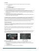
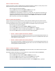
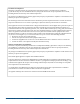
5. Slide the call button module onto the cutout on the side of a sign blade. Insert the module until the
battery and sign blade meet.
6. Attach the sides of the call box; make sure the finger is pointing at the large black button on the left
and right sides.
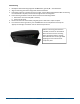
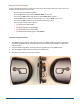
7. Insert and tighten the four screws in the right side of the call box.
Installation and Troubleshooting Tips
1. Identify all programming characteristics before you begin programming or installation.
x Frequency Plan
x Netcode
x Call Box Addresses
x Call Box Modes
2. Program the required parameters into the CB951 Access Points first.
3. Set the corresponding Frequency Plan on each of the call boxes.
Use the first CB951 Access Point to clone the Netcode to all of the call boxes. This will ensure the
same Netcode is being assigned to all devices. You may also clone the Netcode from a known
working call box to all other call boxes. The Netcode cannot be cloned from a call box to an access
point.
4. Program the Alarm Address and Mode of each call box.
5. Install the call box in accordance with store policy, Indyme work order and/or Americans with
Disabilities Act guidelines where applicable.
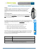
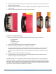
The CB960 Call Box uses one (1) 2/3A 3-volt lithium battery. Always use the same type of battery for
optimum performance. To replace the batteries, remove the 4-phillips screws from the side of the call
box module. Remove the old battery from the battery holder. Install the new 2/3A 3-volt lithium battery
and replace the cover. DO NOT use rechargeable batteries in the call box. The call box will not lose the
programmed characteristics when the batteries are removed.