
Installation Instructions

Technical Document
CB514 Install Instructions 2 P/N: 430223-01 Rev B
5. Press button 1 to increment the tens digit. LED 1 will flash with each press.
6. Press the RESET button when finished with the tens digit.
7. Press button 1 to increment the ones digit. LED 1 will flash with each press.
8. Press the RESET button when finished with the ones digit.
9. The address just programmed should flash back on the LED 1 with a pause between
each digit. (Note: the LED will indicate a zero value by staying on for a longer period of time,
approximately 1 second).
Revised PCA for CB514
Mode Summary:
The new CB514 Call Box PCA has seven operating modes as defined in TSN001:
Wireless Call Boxes. For normal installation, each call box is programmed at the factory.
If it becomes necessary to re-program the call box, please refer to the TSN001 in the
Store Installation and Operation Manual for additional programming features and
requirements. If the manual is not available, please contact the Indyme Help Desk at
800-829-6141 for additional support.
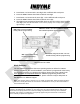
Note: older models of these call boxes are not "Mode" programmable. Before programming these
call boxes, identify what model of circuit board is installed in the unit as per the serial number or
the PCA illustration above.
FCC Notice Of Compliance:
This equipment complies with Part 15 of the FCC Rules. Operation is
subject to the following two conditions: (1) This device must not cause harmful inference and (2) This
device must accept any interference received, including any interference that may cause undesired
operation. Any changes or modifications not expressly approved by the manufacturer could void the
user's authority to operate the equipment.
JP1
Power: mus
t be installed
during call box programming.
JP4
Pulse Width: must be installed for Narrow
Pulse Width operation and programming.
JP3
Mode Program Enable: must be
installed during call box programming.
JP2
: NOT installed during
call box programming.