
User's Manual

Technical Document
430721-01
Rev. E
Indyme Solutions, Inc. 8295 Aero Place San Diego, CA 92123 USA +1.858.268.0717 +1.800.829.6141 Page 5 of 7
RESPOND button is not pressed within 10 minutes, the help button terminates “LED Sequence 1” and the alarm
will timeout.
Mode-6: Alarm Notify & Director Latching
Provides a combination of External Inputs and Director Buttons:
INPUTS 1 and 2 operate in Mode 2; the corresponding front panel button must be pressed to RESET.
Buttons 3 and 4 operate in Mode 5; button “A” is used to RESET active alarms on Buttons 3 & 4.
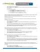
Mode-7: GSF Site Survey (4-Button GSF Help buttons ONLY)
Press any of the 4 buttons to activate the site survey. LED’s 2,3,4 turn on as a 3-second timer, counting down
before the start of the survey. The LED’s will turn off, one per second, (2-3-4) to indicate the count down. When
all 3 LED’s are off, the survey will begin. LED 1 will begin flashing to indicate that the help button is searching for
the strongest AP with the correct Netcode. When the strongest AP is found, the help button will send 10 pings
to that AP and calculate the average RSSI. (Received Signal Strength Indication) The following table describes the
LED results.
LED’s
Meaning
1,2,3,4 on
Excellent - RSSI is -70 dBm or better
2,3,4 on
Good - RSSI is -80 to -71 dBm
3,4 on
Fair - RSSI is -88 to-81 dBm
4 on
Poor - RSSI is -89 dBm or worse
4 flashing
Not connected to an AP
Table – B (LED Flash Sequence)
LED lights solid for the duration that the input alarm exists for a maximum of 5-seconds.
LED continues flashing rapidly for 2-minutes.
LED continues flashing in short bursts indefinitely.
LED ends the flash sequence with two long flashes, then extinguishes when:
Non-latching Operating Modes - the alarm condition clears.
Latching Operating Modes – when associated RESET button is pressed, (if the input alarm condition is
clear).
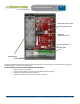
Wiring and Installation
Insure the help button is correctly programmed before installing wiring or mounting the help button. Install the two
green terminal blocks onto the pins of J401 and J501 respectively. J401 contains 4-pairs of screw terminals
corresponding to inputs 1-4. J501 has 1-pair of screw terminals, this connection is not used. Insert the wires through the
hole in the back of the help button. Insert each wire into the corresponding input screw terminal; inputs 1-4, left to
right. Secure the wires by tightening the screws. Verify the power jumper JP201 is installed and the corresponding
power source is installed/connected. Test the help button for proper operation before final installation.