
User's Manual

Technical Document
CB529A Program & Install Instructions 4 P/N 430721-00 Rev C
Wiring and Installation
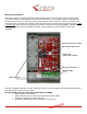
Insure the call box is correctly programmed before installing wiring or mounting the call box. Install the two
green terminal blocks onto the pins of J401 and J501 respectively. J401 contains 4-pairs of screw terminals
corresponding to inputs 1-4. J501 has 1-pair of screw terminals, this connection is not used. Insert the wires
through the hole in the back of the call box. Insert each wire into the corresponding input screw terminal;
inputs
1-4, left to right. Secure the wires by tightening the screws. Verify the power jumper JP201 is installed and the
corresponding power source is installed/connected. Test the call box for proper operation before final
installation.
J401: Input Terminals 1- 4
J501: NOT USED
JP201: Power Source Jumper
J201: External Power Jack
JP301--304:
Input Circuit Jumpers
Mountin
g
Holes
Using the installation hardware provided, install the call box in a secure location. Ensure the wires are properly
secured and will not pull out of the call box.
DO NOT MOUNT THE CALL BOX IN OR NEAR THE FOLLOWING;
Moist or damp environments.
Radio Frequency devices that may interfere with call box signals.
Outdoors or exposed to outdoor elements.
Excessive vibration which may cause wires to come loose.
PRE-RELEASE