
User's Manual
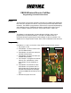
Table Of Contents

Indyme Electronics, Inc.
Programming Mode and House Code.
Use Button 1 to select the Mode and use Button 7 to set the House Code. When
finished, use Button 12 to SAVE the programmed Mode and House code.
1. Put jumper on JP2.(JP2 is located right next to JP3)
2. Press Button 1 to select which mode.
(One press for mode 1, twice for mode 2,
three times for mode 3 and four times for mode 4.)
3. Press Button 7 to select which house code set. (One press for house
code set 1, press twice for House Code set 2.)
4. Press Button 12 to save the programmed Mode and House Code. The TX
LED will flash which mode the CB520 was programmed for and the
CLEAR LED will flash which house code set has been selected.
5. Remove the jumper from JP2.
Setting the Normally Open / Normally Closed Jumpers
1. To set for normally open remove the jumper from JP4.
2. To set for normally closed put the jumper on JP4.
When either of the above is done, the CB520 must be reset by powering
down the call box (removing the jumper from JP1) and then powering it back
up and pressing S1.
Modes of Operation
• Mode 1 - Director Call Box with 15 Second Time-out (similar to CB514-3)
Press a channel button to trigger alarm state; the TX and ACTIVE LED flash.
The ACTIVE LED continues to flashes for approximately 15 seconds, then
extinguishes with no reset sent.
If the channel button is pressed again within a preset (variable) time the
ACTIVE LED will flash for another 15 seconds and the alarm will escalate to
the next up-group, depending on the CU4400 programming.
• Mode 2 - Variable Response Reset (similar to the CB700A mode 5)
An external switch contact transition will trigger a button 12 "alarm state"
(contact shared with button 12), the ACTIVE LED flashes; and continues to
flash for 300 seconds. Pressing any of the other 11 buttons extinguishes the
ACTIVE LED, sends a SET transmission for the pressed channel button and
a reset transmission for button 12.
• Mode 3 - Director with External Input and Reset
Button 1-11 works the same as Mode 1 (normal director function). The
external input is enabled and when triggered, sends a shopper call box
transmission for button 12. The ALARM LED comes on solid for one second
and the ACTIVE LED flashes at a decreased rate (continues to flash for 300
seconds). If the alarm state is removed, the CLEAR LED will come on solid
for one second with no reset sent. Pressing button 12 sends a reset
transmission for button 12 and extinguishes the ACTIVE LED (if lit).
CB520 Programming Instructions
2
P/N 430489-00 Rev D