
User's Manual

Technical Document
430735-00
Rev. D
Indyme Solutions, Inc. 8295 Aero Place San Diego, CA 92123 USA +1.858.268.0717 +1.800.829.6141Page 3 of 4
INSTALLATION AND TROUBLESHOOTING TIPS
1. Identify all programming characteristics before you begin programming or installation.
Help Button Addresses
Help Button Mode
Mounting Location
2. Program the Alarm Address and Mode of each help button.
3. Install the help button in accordance with store policy, Indyme work order and/or Americans with Disabilities
Act guidelines where applicable.
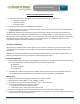
The CB461 help button uses two 2/3A-size 3.0-volt lithium batteries. Always use the same type of battery for
optimum performance. DO NOT use rechargeable batteries in the help button. To replace the batteries, remove
the help button from its mounting location. Turn the help button over to the back of the help button. Remove the
old batteries from the battery holders. Install the new lithium batteries. The help button does not lose the
programmed characteristics when the batteries are removed.
Location Considerations
Help buttons are typically located at cash registers, service counters or other areas in which customers require
assistance. Stores and installers should be aware of the Americans with Disabilities Act (ADA) requirements for
accessibility.
Help buttons use a low powered transmitter, and operate best with a clear line of sight to the nearest receiver. Tall
shelving, merchandise and metal signs can block or reduce the help button signal.
Install the Help button
1. Verify help button placement with the Store Manager and according to provided instructions. Determine the best
mounting method before installing the help button, verify address programming.
Wall Mount
Counter Top Mount
Store Shelving
2. The CB461 has 2-different mounting options available; wall or counter top. Choose the appropriate option for
your situation. Reference the CB64 Counter Top Installation document for details. P/N:430738-00
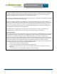
Wall Mounting
1. Identify the desired mounting height for the SET button, subtract 2-inches.
2. Mark the first hole at this height. (1
st
hole = HEIGHT – 2inches)
3. Mark the second hole 4-inches above the first. (2
nd
hole = 1
st
hole + 4inches)
4. Insert mounting hardware in the two holes as follows;
a. wall anchors and screws if drywall or masonry
b. sheet metal screws or wood screws if the surface is solid
5. Place the mounting holes on the back of the help button over the screw heads, pull down slightly.
6. From the final mounting location, press the SET button on the help button and verify the appropriate message
is broadcast over the desired output device.