
Data Sheet

Ref. IS.MDUINO.XXX
10.7 RTC
M-Duino RTC Module is based on the DS1307 Chip. This chip works with the I2C protocol
communication, so it is required to have enabled the I2C protocol.
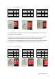
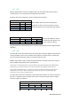
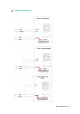
4 switches have to be configured in order to enable the RTC features:
RTC SCL & RTC SDA must be set to ON mode to
enable the I2C wires to the RTC. If they are in OFF
mode, the Arduino won’t communicate with the RTC.
I2C must be enabled in order to
communicate with the RTC. See
section 11 I2C to enable it.
Using the boards of Industrial Shields, there is a library that simplifies the RTC implementation
called RTC.
10.8 uSD
The micro SD uses the SPI communication to interact with the Arduino Mega. The SPI protocol
is always enabled, as there are no switches that configure it. However there is a switch that
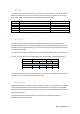
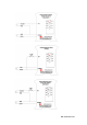
must be placed to ON mode in order to communicate with the uSD:
D53(SD): If this Switch is ON, it enables the Chip Select of the microSD socket. If this switch is
OFF, it disables the Chip Select of the microSD socket.
*If the D Zone is an Analog Shield, Q2.0 is also related with D53. Being D53 in ON Mode the Q2.0 MUST NOT be
used because it can corrupt the microSD. In order to use the Q2.0 the switch D53(SD) must be set to OFF.
*If the D Zone is a Relay Shield there is no problem and it can be set always to ON. Q2.0 of the Relay Shield is
related with D12, so it doesn’t affect in any case to the microSD. The pin53 is not connected at all to any
input/output, it only connects to the uSD chip select.
The uSD socket is found in the TOP part of the communication Shields, so in the frontal part of
the PLC, it is required to open the plastic found in the frontal part and the socket is located
under the supply of the Arduino.
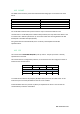
LEFT ZONE
SWITCH
ON
OFF
NC
-
-
NC
-
-
RTC SCL
RTC
-
RTC SDA
RTC
-
Switch
Analog Shield
Relay Shield
ON
OFF
ON
OFF
SCL/I2.6
I2.6
SCL
I2.1
SCL
SDA/I2.5
I2.5
SDA
I2.0
SDA
LEFT ZONE
Switch
Analog Shield
Relay Shield
ON
OFF
ON
OFF
uSD
D53(SD)
D53(SD)
Q2.0
D53(SD)
-