
Data Sheet

Ref. IS.MDUINO.XXX
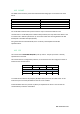
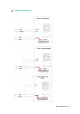
10.4 SPI
The M-Duino pins used for the SPI bus are summarized in the table below. For SPI bus MISO,
MOSI and CLOCK pins are common to all the connected devices to the M-Duino, conversely,
each of the connected devices will have a single and dedicated SS pin.
Function
M-Duino connection
Mega board pin
MISO
50 S0
50
MOSI
51 SI
51
CLOCK
52 SCK
52
Reset
Reset
Reset
SS
SCL/SDA/RX0/TX0/RX1/TX1/RX3/TX3/Pin2/Pin3
21/20/1/0/19/18/15/14/2/3
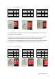
Check the switch configuration at section 8 to enable SS pins.
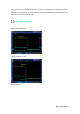
10.5 TTL
M-Duino has three TTL ports, RX0/TX0 and RX1/TX1, RX3/TX3. TTL0 is accessed with the
function Serial (pins 0 and 1 of the Arduino Mega). TTL1 is accessed with the function Serial1
(pins 18 and 19 of the Arduino Mega). TTL3 is accessed with the function Serial3 (pins 14 and
15 of the Arduino Mega).
If using TTL3, the RS-232 communication protocol is totally disabled as it also uses the Serial 3.
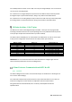
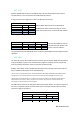
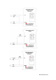
In order to use the TTL pins the configuration of the switches have to be the following one:
If the switches RX1/I1.6(I1.1) & TX1/I1.5(I1.0) are in OFF mode, the RX1/TX1 will be enabled. In
order to use TTL3 these switches must be in OFF mode.
10.6 Ethernet
M-Duino Ethernet port controller is based on w5500 IC, which is the compatible IC compatible
with Arduino Ethernet2 Shield libraries. All Ethernet shield Arduino libraries are compatible
with the M-DUino. In the M-Duino, W5500 IC communicates to the Mega board via SPI bus (SS
Arduino Mega pin 10).
Using the boards of Industrial Shields, there is a library that simplifies the Ethernet
implementation called Ethernet2.
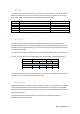
Switch
Analog Shield
Relay Shield
ON
OFF
ON
OFF
C ZONE
RX1/I1.6
I1.6
RX1
I1.1
RX1
TX1/I1.5
I1.5
TX1
I1.0
TX1