
Data Sheet

Ref. IS.MDUINO.XXX
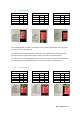
For the Relay Shield if a switch is set to ON, it can only act as Digital Output. If it is set to OFF it
can only act as an Analog Output.
If it is desired to use a Digital Output the pin must be set to ON and the pin that will provide
this digital output is represented with QX.X, being X any number of the tables above.
If it is desired to use an Analog Output the pin must be set to OFF and the pin that will provide
this analog output is represented with AX.X, being X any number of the tables above.
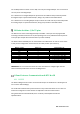
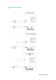
M-Duino Arduino I/Os 5V pins
The M-Duino has some of the Mega board pins available. These pins can be programmed
according to Arduino features such as I/Os operating at 5V or any additional features present
in the pins (for example I2C communication in pins SCL and SDA).
The Arduino board available pins are summarized in the table below. In order to access some
of this pins the configuration switch must be set to OFF position (see section 8).
IMPORTANT: Do not connect the terminals in the chart above to voltages higher than 5V.
These terminals provide direct access to the Mega board.
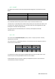
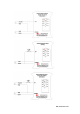
A Zone Features: Communications & RTC & uSD
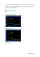
10.1 RS-232
The Arduino Mega function code to access the RS-232 port in the M-Duino is Serial2 (pins 16
and 17 of the Arduino Mega).
For the RS-232 communication protocol there isn’t any switch that affects it. So it does not
matter the configuration of the switches to implement a RS-232 communication.
Using the boards of Industrial Shields, there is a library that simplifies the RS-232
implementation.
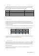
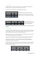
M-Duino terminal
Arduino pin
Enable Arduino pin
SCL
21
Communication switch: OFF
SDA
20
Communication switch OFF
RX0
0
TX0
1
RX1
19
Communication switch: OFF
TX1
18
Communication switch: OFF
RX3
15
TX3
14
Pin 3
3
Communication switch: OFF
Pin 2
2
Communication switch: OFF