M-DUINO FAMILY M-Duino Family User Guide: Ref. IS.MDUINO.
Ref. IS.MDUINO.
Ethernet PLC User Guide Revised March 2018 Ref. IS.MDUINO.
Preface This User Guide is been implemented by Boot & Work, S.L. working under the name Industrial Shields. Purpose of the manual The information contained in this manual can be used as a reference to operating, to functions, and to the technical data of the signal modules, power supply modules and interface modules. Intended Audience This User Guide is intended for the following audience: Persons in charge of introducing automation devices. Persons who design automation systems.
Application Considerations and Warranty Read and Understand this Manual Please read and understand this manual before using the product. Please consult your comments or questions to Industrial Shields before using the product. Application Consideration THE PRODUCTS CONTAINED IN THIS DOCUMENT ARE NOT SAFETY RATED. THEY SHOULD NOT BE RELIED UPON AS A SAFETY COMPONENT OR PROTECTIVE DEVICE FOR ENSURING SAFETY OF PERSONS, AS THEY ARE NOT RATED OR DESSIGNED FOR SUCH PURPOSES.
Disclaimers Weights and Dimensions Dimensions and weights are nominal and they are not used for manufacturing purposes, even when tolerances are shown. Performance Data Performance data given in this manual is provided as a guide for the user in determining suitability and does not constitute a warranty. It may represent the result of INDUSTRIAL SHIELDS’s test conditions, and the users most correlate it to actual application requirements.
Warranty and Limitations of Liability Warranty Industrial Shields’s exclusive warranty is that the products are free from defects in materials and workmanship for a period of one year (or other period if specified) from date of sale by Industrial Shields. INDUSTRIAL SHIELDS MAKES NO REPRESENTATION OR WARRANTY, EXPRESS OR IMPLIED, REGARDING MERCHANABILITY, NON-INFRINGEMENT, OR FITNESS FOR PARTICULAR PURPOSE OF THE PRODUCTS.
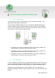
Table of Contents General Description M-DUINO FAMILY product ....................................................... 10 1.1 Zone - Nomenclature ...................................................................................................... 10 1.2 Zone Distribution............................................................................................................. 10 1.3 A Zone Features........................................................................................................
8.3 Relay Shield ..................................................................................................................... 31 M-Duino Arduino I/Os 5V pins ................................................................................. 32 A Zone Features: Communications & RTC & uSD.................................................. 32 10.1 RS-232 ............................................................................................................................. 32 10.2 RS-485 .....
General Description M-DUINO FAMILY product 1.1 Zone - Nomenclature The nomenclature shown in this point will be used in the whole User Guide, so it is important to understand this nomenclature. D ZONE C ZONE B ZONE A ZONE D ZONE C ZONE B ZONE A ZONE A ZONE B ZONE C ZONE D ZONE The nomenclature to differentiate the zones is based on the Alphabet, being A the shield from below and D the shield from above. Having a B and a C in the middle of them.
The distribution of the different features that provide the M-Duino Family is the following one: Shield B Zone C Zone D Zone 13 Inputs (13 Digital inputs, 6 of which can work as Analog Input) 13 Inputs (13 Digital inputs, 6 of which can work as Analog Input) 11 Inputs (11 Digital Inputs, 4 of which can work as Analog Input) 8 Outputs (8 Digital Outputs, 3 of which can work as Analog Output) 6 Inputs (6 Digital Inputs, 4 of which can work as Analog Input) 8 Outputs (8 Digital Outputs, 3 of which can
1.3 A Zone Features Shield A Zone Communication Shield (1x) Ethernet (1x) USB (1x) I2C (3x) TTL (1x) RS-232 (1x) HALF/FULL Duplex RS-485 (1x) SPI external Port (1x) RTC (1x) uSD Socket This is the list of our products depending on the combination of the shields. As it is already said above the A Zone is totally common for all the M-Duino Family.
1.4 Mechanical dimension M-Duino 1 BLOCK I/Os M-Duino 2 BLOCKS I/Os M-Duino 3 BLOCKS I/Os Ref. IS.MDUINO.
1.5 General Features CONECTABLE PLC ARDUINO 24Vcc M-DUINO B+C+D MODEL TYPE B Zone B+C Zone Zone Input Voltage I max. Size Clock Speed Flash Memory SRAM EEPROM Communications 12 to 24Vdc Fuse protection (2.5A) Polarity protection 1.5A 101x119.5x70.1 101x119.5x94.7 101x119.5x119.
Technical Specifications: 2.1 General Specifications: Item M-DUINO B ZONE Power supply voltage DC power supply Operating voltage range DC power supply 11.4 to 25.4Vdc Power consumption DC power supply 30VAC max. External power supply M-DUINO B+C+D ZONE 12 to 24Vdc Power supply voltage 24Vdc Power supply output capacity 700Ma Insulation resistance M-DUINO B+C ZONE 20MΩ min.at 500Vdc between the AC terminals and the protective earth terminal. Dielectric strength 2.
Precautions Read this manual before attempting to use the M-Duino PLC and follow its descriptions for reference during operation. 3.1 Arduino Board All M-Duino family PLCs include Arduino Mega Board as controller. 3.2 Intended Audience This manual is intended for technicians, which must have knowledge on electrical systems. 3.3 General Precautions The user must operate M-Duino according to the performance specifications described in this manual.
Steps: 1. Open Arduino IDE and go to: “File -> Preferences” located in the top left corner. 2. In Additional Boards Manager URLs write the following: http://apps.industrialshields.com/main/arduino/boards/package_industrialshields_index.json 3. Press OK to save the changes. 4. Go to: Tools -> Board: … -> Boards Manager Ref. IS.MDUINO.
5. Search for “industrialshields” on the browser. 6. Click install (selecting the latest version). Following this steps you will be able to see now the Industrial Shields Boards: Once it is selected the Ardbox Family or M-Duino family an extra option will appear on Tools: There, it can be selected the exact model for every family. Ref. IS.MDUINO.
Also there are some examples of programming in File -> Examples -> M-Duino Family. Furthermore there are some extra libraries that can be found in Industrial Shields github. https://github.com/IndustrialShields/ How to connect PLC Arduino to PC - Connect USB port from PLC to PC. NOTE: M-Duino Family use USB-B cable. - Open Arduino IDE interface: - Select Industrial Shields boards -> M-Duino Family Ref. IS.MDUINO.
- Select the correct M-Duino Board. - Select correct port. How to connect PLC to power supply - M-Duino Family PLCs are 12-24Vdc supplied. IMPORTANT: The polarity IS NOT REVERSAL! - Make sure that the live and GND connector of the power supply match the PLC. - Make sure that the power supply mains output is not higher than 24Vdc. Ref. IS.MDUINO.
- Suggested power suppliers * Not recommended for industrial applications. The Jack connector needs to be removed and use the live and GND connectors. M-duino Family Pinout 7.
Base (common unit) AREF IOREF2 IOREF1 7Vdc Gnd 3.3Vdc GND 5Vdc GND AREF IOREF2 IOREF1 7Vdc Gnd 3.3Vdc Gnd 5Vdc Gnd Function Arduino Pin M-Duino Connector A Zone Arduino PIN Arduino PIN Arduino PIN GND Arduino PIN GND GND Ethernet Connector Arduino Reset button Power USB programmer connector Autoreset *NOTE: Autoreset. Arduino mega has auto reset when using serial communication code. Set switch to OFF when using serial communication. When uploading code to Arduino Mega set switch to ON. Ref. IS.
7.2 7.2.1 B Zone Analog Shield I0.12 I0.11 I0.10 I0.9 I0.8 I0.7 (-)I0.6/INT1 I0.6/INT12 (-)I0.5/INT0 I0.5/INT02 (-)I0.4 I0.4 (-)I0.3 I0.3 (-)I0.2 I0.2 (-)I0.1 I0.12 (-)I0.0 I0.02 A5 A4 A3 A2 A1 A0 3 2 26 25 24 23 22 Function 1 Arduino Pin M-Duino Connector B Zone Analog/ Digital In Analog/ Digital In Analog/ Digital In Analog/ Digital In Analog/ Digital In Analog/ Digital In GND I0.6 Interrupt 1 In GND I0.5 Interrupt 0 In GND I0.4 Digital Input GND I0.3 Digital Input GND I0.2 Digital Input GND I0.
7.2.2 Relay Shield R0.8 R0.7 R0.6 R0.5 R0.4 A0.21 A0.11 A0.01 GND Q0.21 Q0.11 Q0.01 GNDCOM 24VCOM 37 38 39 40 24 6 5 4 GND 6 5 4 --- Function 3 Arduino Pin M-Duino Connector B Zone Relay Out Relay Out Relay Out Relay Out Relay Out Analog Out Analog Out Analog Out GND Digital/PWM Out Digital/PWM Out Digital/PWM Out External Isolated Out Gnd External Isolated Out Vdc RELAY Outputs ANALOG Output (Switch Configuration) DIGITAL/PWM Outputs (isolated) Top Zone Led indicator I/Os state . R0.3 R0.
7.3 7.3.1 C Zone Analog Shield (C Zone) I1.12 I1.11 I1.10 I1.9 I1.8 I1.7 (-)I1.6/INT1 I1.6/INT12 (-)I1.5/INT0 I1.5/INT02 (-)I1.4 I1.4 (-)I1.3 I1.3 (-)I1.2 I1.2 (-)I1.1 I1.1 (-)I1.0 I1.0 A11 A10 A9 A8 A7 A6 NC 19 NC 18 NC 31 NC 30 NC 29 NC 28 NC 27 Function 4 Arduino Pin M-Duino Connector C Zone Analog/ Digital In Analog/ Digital In Analog/ Digital In Analog/ Digital In Analog/ Digital In Analog/ Digital In GND I1.6 Interrupt 1 In GND I1.5 Interrupt 0 In GND I1.4 Digital Input GND I1.
7.3.2 Relay Shield C Zone R1.8 R1.7 R1.6 R1.5 R1.4 A1.21 A1.11 A1.01 GND Q1.21 Q1.11 Q1.01 GNDCOM 24VCOM 42 43 44 45 29 11 10 8 GND 11 10 8 --- Function 5 Arduino Pin M-Duino Connector B Zone Relay Out Relay Out Relay Out Relay Out Relay Out Analog Out Analog Out Analog Out GND Digital/PWM Out Digital/PWM Out Digital/PWM Out External Isolated Out Gnd External Isolated Out Vdc RELAY Outputs ANALOG Output (Switch Configuration) DIGITAL/PWM Outputs (isolated) Top Zone Led indicator I/Os state .
7.4 7.4.1 D Zone Analog Shield (D Zone) I2.12 I2.11 I2.10 I2.9 I2.8 I2.7 (-)I2.6/INT1 I2.6/INT12 (-)I2.5/INT0 I2.5/INT02 (-)I2.4 I2.4 (-)I2.3 I2.3 (-)I2.2 I2.2 (-)I2.1 I2.1 (-)I2.0 I2.0 A15 A14 A13 A12 NC 21 NC 20 NC 35 NC 34 NC 33 NC 32 Function 6 Arduino Pin M-Duino Connector D Zone Analog/ Digital In Analog/ Digital In Analog/ Digital In Analog/ Digital In Analog/ Digital In Analog/ Digital In GND I2.6 Interrupt 1 In GND I2.5 Interrupt 0 In GND I2.3 Digital Input GND I2.2 Digital Input GND I2.
7.4.2 Relay Shield D Zone R2.8 R2.7 R2.6 R2.5 R2.4 A2.2 A2.11 A2.01 GND Q2.2 Q2.11 Q2.01 GNDCOM 24VCOM 47 48 49 34 13 12 GND 13 12 --- Function 7 Arduino Pin M-Duino Connector D Zone RELAY Outputs Relay Out Relay Out Relay Out Relay Out Analog Out Analog Out GND Digital/PWM Out Digital/PWM Out Digital/PWM Out External Isolated Out Gnd External Isolated Out Vdc ANALOG Output (Switch Configuration) DIGITAL/PWM Outputs (isolated) Top Zone Led indicator I/Os state . R2.3 R2.2 R2.1 GND I2.5 I2.
Switch configuration 8.1 A Zone: Communications Switch SCL/I2.6 SDA/I2.5 RX1/I1.6 TX1/I1.5 Pin 3/I0.6 Pin 2/I0.5 D53(SD) FD RS-485 HD LEFT ZONE Analog Shield ON OFF D ZONE I2.6 SCL I2.5 SDA C ZONE I1.6 RX1 I1.5 TX1 B ZONE I0.6 Pin 3 I0.5 Pin 2 uSD & RS-485 D53(SD) Q2.0 HD FD Relay Shield ON OFF I2.1 I2.0 SCL SDA I1.1 I1.0 RX1 TX1 I0.1 I0.0 Pin 3 Pin 2 D53(SD) HD FD *Although the Serigraphy of the Switches will only reference to the Analog Shields, if a Relay Shield is connected the IX.
4. Pin 3/I0.6: Choosing between Pin 3 or the input I0.6. If this switch is ON, it enables the I0.6 input and disables the Pin 3. If this switch is OFF, it enables Pin 3 and disables I0.6. If it is a Relay Shield I0.6 is changed for I0.1 3. Pin 2/I0.5: Choosing between Pin 2 or the input I0.5. If this switch is ON, it enables the I0.5 input and disables the Pin 2. If this switch is OFF, it enables Pin 2 and disables I0.5. If it is a Relay Shield I0.5 is changed for I0.0 2.
8.2 Analog Shield B ZONE SWITCH ON OFF NC Q0.7 Q0.7 A0.7 Q0.6 Q0.6 A0.6 Q0.5 Q0.5 A0.5 C ZONE SWITCH ON OFF NC Q1.7 Q1.7 A1.7 Q1.6 Q1.6 A1.6 Q1.5 Q1.5 A1.5 D ZONE SWITCH ON OFF NC Q2.7 Q2.6 Q2.6 A2.6 Q2.5 Q2.5 A2.5 For the Analog Shield if a switch is set to ON, it can only act as Digital Output. If it is set to OFF it can only act as an Analog Output. If it is desired to use a Digital Output the pin must be set to ON and the pin that will provide this digital output is represented with QX.
For the Relay Shield if a switch is set to ON, it can only act as Digital Output. If it is set to OFF it can only act as an Analog Output. If it is desired to use a Digital Output the pin must be set to ON and the pin that will provide this digital output is represented with QX.X, being X any number of the tables above. If it is desired to use an Analog Output the pin must be set to OFF and the pin that will provide this analog output is represented with AX.X, being X any number of the tables above.
10.2 RS-485 For RS485 communication protocol the defined Arduino Mega pins are showed in the chart below. Function DI RO RE DE Arduino Pin 14 15 11 46 For the RS-485 communication protocol there is only one switch that affects in this communication. The RS-485 protocol will be always enabled, the only switch that affects is the one called “FD rs-485 HD” (See Section 9). This switch makes the choosing between RS-485 Half Duplex or RS-485 Full Duplex (RS-422).
10.4 SPI The M-Duino pins used for the SPI bus are summarized in the table below. For SPI bus MISO, MOSI and CLOCK pins are common to all the connected devices to the M-Duino, conversely, each of the connected devices will have a single and dedicated SS pin. Function M-Duino connection MISO 50 S0 MOSI 51 SI CLOCK 52 SCK Reset Reset SS SCL/SDA/RX0/TX0/RX1/TX1/RX3/TX3/Pin2/Pin3 Check the switch configuration at section 8 to enable SS pins. Mega board pin 50 51 52 Reset 21/20/1/0/19/18/15/14/2/3 10.
10.7 RTC M-Duino RTC Module is based on the DS1307 Chip. This chip works with the I2C protocol communication, so it is required to have enabled the I2C protocol. 4 switches have to be configured in order to enable the RTC features: SWITCH NC NC RTC SCL RTC SDA LEFT ZONE ON RTC RTC Switch SCL/I2.6 SDA/I2.5 OFF - Analog Shield ON OFF I2.6 SCL I2.5 SDA RTC SCL & RTC SDA must be set to ON mode to enable the I2C wires to the RTC. If they are in OFF mode, the Arduino won’t communicate with the RTC.
Using the boards of Industrial Shields, there is a library that simplifies the uSD implementation called SD. It is the same as the Arduino library, with the only modification of using the pin 53 to select the Chip Select of the uSD chip. I/O technical details: Digital Output Waveform: Digital Out-put Turn-off: PWM Waveform: Ref. IS.MDUINO.
Analog Out Turn On: Analog Out Turn-Off: Analog /Digital input Turn-on: Ref. IS.MDUINO.
Ref. IS.MDUINO.
Typical Connections Ref. IS.MDUINO.
Ref. IS.MDUINO.
Ref. IS.MDUINO.
Ref. IS.MDUINO.
Connector details: The connector inside the PLCs that mounts on the PCB is MC 0,5/10-G-2,5 THT – 1963502 from Phoenix contact. MC0,5/10-G-2,5THT For I/O and power supply there is a FK-MC 0,5/10-ST-2,5 - 1881406 connector from Phoenix contact. FK-MC 0,5/10-ST-2,5 Connection details: Article reference MC 0,5/10-G-2,5 THT Height 8,1mm Pitch 2,5mm Dimension 22,5mm Pin dimensions 0,8x0,8mm Pin spacing 2,50mm Article reference FK-MC 0,5/10-ST-2,5 Rigid conduit section min.
Mechanical Characteristics - Dimension M-duino Family: - DIN Rail mounting Ref. IS.MDUINO.
About Industrial Shields: Direction: Fàbrica del Pont, 1-11 Zip/Postal Code: 08272 City: Sant Fruitós de Bages (Barcelona) Country: Spain Telephone: (+34) 938 760 191 / (+34) 635 693 611 Mail: industrialshields@industrialshields.com Ref. IS.MDUINO.