
User Guide

Ref. IS.MDuino.42+ Rev. 1: 30-08-2019
34
10.3 I2C
The I2C protocol is meant to work in a pull-up configuration. A pull-up configuration means
that when the pin is at rest (nothing connected to it) it always reads a HIGH value. In this case
it reads 5V when nothing is connected. The pull-up configuration is stablished by default in
these pins.
If it is meant to work them as a GPIO at 5V, it has to be considered that they are pull-up inputs.
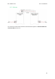
10.4 SPI
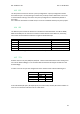
The M-Duino pins used for the SPI bus are summarized in the table below. For SPI bus MISO,
MOSI and CLOCK pins are common to all the connected devices to the M-Duino, conversely,
each of the connected devices will have a single and dedicated SS pin.
Function
M-Duino connection
Mega board pin
MISO
50 S0
50
MOSI
51 SI
51
CLOCK
52 SCK
52
Reset
Reset
Reset
SS
SCL/SDA/RX0/TX0/RX1/TX1/RX3/TX3/Pin2/Pin3
21/20/1/0/19/18/15/14/2/3
Check the switch configuration at section 8 to enable SS pins.
10.5 TTL
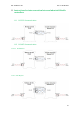
M-Duino has two TTL ports, RX0/TX0, RX1/TX1. TTL0 is accessed with the function Serial (pins 0
and 1 of the Arduino Mega). TTL1 is accessed with the function Serial1 (pins 18 and 19 of the
Arduino Mega).
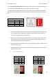
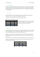
In order to use the TTL pins the configuration of the switches have to be the following one:
If the switches RX1/I1.6(I1.1) & TX1/I1.5(I1.0) are in OFF mode, the RX1/TX1 will be enabled. In
order to use TTL3 these switches must be in OFF mode.
Switch
Analog Shield
ON
OFF
C ZONE
RX1/I1.6
I1.6
RX1
TX1/I1.5
I1.5
TX1