
Data Sheet

Page
19
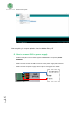
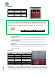
NOTE: Although in the TOP ZONE serigraphy it is shown Q0.9 & Q0.8 pins, in the reality they
are I0.3 I0.2 pins respectively. Additionally although the serigraphy only is expressed for the
RS485 it is also the same for the RS232. So if it is desired to enable any of the Hardware Serial
connection this is the function of these switches. See chapter 8 for more information
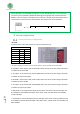
8. Switch configuration
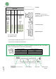
General Switches Configuration
LEFT ZONE.
Communications and inputs/outputs can not work simultaneously.
*I2C switch serigraphy is turned around. It should be: (SDA-D2 , SCL-D3). RX-RS485 should be RE-RS485
6. DE-RS485 – If this switch is ON, the A0.2-Q0.2 switch must be set to OFF. Being in ON mode
it enables DE for the RS-485.
5. A0.2-Q0.2 – If this switch is ON, the DE-RS485 switch must be set to OFF. Being in ON mode
it enables the outputs A0.2-Q0.2.
4. RE-RS485 – If this switch is ON, the A0.1-Q0.1 switch must be set to OFF. Being in ON mode
it enables EE for the RS-485.
3. A0.1-Q0.1 – If this switch is ON, the RE-RS485 switch must be set to OFF. Being in ON mode
it enables the outputs A0.1-Q0.1.
2. SDA-D2/I0.0 – Choosing between SDA (I2C) and I0.0. If this switch is ON, the I0.0 input will
be enabled and the SDA will be disabled. If this switch is OFF, the SDA will be now available
and I0.0 disabled
1. SCL-D3/Q0.6 – Choosing between SCL (I2C) and Q0.6. If this switch is ON, the Q0.6 input will
be enabled and the SCL will be disabled. If this switch is OFF, the SCL will be now available and
Q0.6 disabled.
I0.3
RS485/RS232 HS
I0.2
RS485/RS232 HS
LEFT ZONE
SWITCH
OFF
ON
DE-RS485
A0.2-Q0.2*
DE-RS485
D10/A0.2-Q0.2
DE-RS485
A0.2-Q0.2
RE-RS485*
A0.1-Q0.1*
RE-RS485
D11/A0.1-Q0.1
RE-RS485
A0.1-Q0.1*
SDA-D2/I0.0*
SDA-D2
I0.0
SCL-D3/Q0.6*
SCL-D3
Q0.6